
Safety Instructions ............. 2, 3
Operating Instructions
Controls ........................... 4–6
Care and Cleaning
Air Filter ..............................6
Outdoor Coils .........................6
Installation Instructions ...... 7–13
Troubleshooting Tips ............14
Normal Operating Sounds ............14
Consumer Support
Consumer Support ..........Back Cover
Warranty ............................16
49-7715-1 11-15 GE
Owner’s Manual and
Installation Instructions
Write the model and serial numbers here:
Model # _________________________
Serial # __________________________
Find these numbers on a label on the side of
the air conditioner.
Air Conditioners
GEAppliances.com
Room
Acondicionador
de aire
Manual del propietario
y instrucciones de
instalación
La sección en español empieza en la página 17
AEH24

2
IMPORTANT SAFETY INFORMATION.
READ ALL INSTRUCTIONS BEFORE USING.
For your safety, the information in this manual must be followed to minimize the risk of fire, electric shock or personal
injury.
Use this appliance only for its intended purpose as
described in this Owner’s Manual.
This air conditioner must be properly installed in
accordance with the Installation Instructions before it
is used.
Never unplug your air conditioner by pulling on the
power cord. Always grip plug firmly and pull straight
out from the receptacle.
Replace immediately all electric service cords that
have become frayed or otherwise damaged. A
damaged power supply cord must be replaced
with a new power supply cord obtained from the
manufacturer and not repaired. Do not use a cord
that shows cracks or abrasion damage along its
length or at either the plug or connector end.
Turn the unit OFF and unplug your air conditioner
before cleaning.
GE does not support any servicing of the air
conditioner. We strongly recommend that you do not
attempt to service the air conditioner yourself.
For your safety…do not store or use combustible
materials, gasoline or other flammable vapors or
liquids in the vicinity of this or any other appliance.
All air conditioners contain refrigerants, which under
federal law must be removed prior to product
disposal. If you are getting rid of an old product
with refrigerants, check with the company handling
disposal about what to do.
If the receptacle does not match the plug, the
receptacle must be changed out by a qualified
electrician.
These R410A air conditioning systems require
contractors and technicians to use tools, equipment
and safety standards approved for use with this
refrigerant. DO NOT use equipment certified for
R22 refrigerant only.
SAFETY PRECAUTIONS
This is the safety alert symbol. This symbol alerts you to potential hazards that can kill or hurt you and others. All safety
messages will follow the safety alert symbol and the word “DANGER”, “WARNING”, or “CAUTION”. These words are defined as:
Indicates a hazardous situation which, if not avoided, will result in death or serious injury.
Indicates a hazardous situation which, if not avoided, could result in death or serious injury.
Indicates a hazardous situation which, if not avoided, could result in minor or moderate injury.
SAFETY INFORMATION
WARNING
DANGER
CAUTION
WARNING

3
Do not, under any circumstances, cut or remove the third
(ground) prong from the power cord. For personal safety,
this appliance must be properly grounded.
DO NOT use an adapter plug with this appliance.
The power cord of this appliance is equipped with a
3-prong (grounding) plug which mates with a standard
3-prong (grounding) wall outlet to minimize the
possibility of electric shock hazard from this appliance.
Power cord includes a current interrupter device. A
test and reset button is provided on the plug case. The
device should be tested on a periodic basis by first
pressing the TEST button and then the RESET button
while plugged into the outlet. If the TEST button does
not trip or if the RESET button will not stay engaged,
discontinue use of the air conditioner and contact a
qualified service technician.
Have the wall outlet and circuit checked by a qualified
electrician to make sure the outlet is properly grounded.
Where a 2-prong wall outlet is encountered, it is your
personal responsibility and obligation to have it replaced
with a properly grounded 3-prong wall outlet.
The air conditioner should always be plugged into its
own individual electrical outlet which has a voltage
rating that matches the rating plate.
This provides the best performance and also prevents
overloading house wiring circuits which could cause a
fire hazard from overheated wires.
See the Installation Instructions, Electrical Requirements
section for specific electrical connection requirements.
HOW TO CONNECT ELECTRICITY
GEAppliances.com
USE OF EXTENSION CORDS
READ AND FOLLOW THIS SAFETY INFORMATION
CAREFULLY
.
SAVE THESE INSTRUCTIONS
RISK OF FIRE. Could cause serious injury or death.
• DO NOT use an extension cord with this Window Air
Conditioner.
• DO NOT use surge protectors or multi-outlet adaptors
with this Window Air Conditioner.
RECYCLING INFORMATION
For appliance recycling information please visit www.
geappliances.com/recycling.
WARNING

4
About the controls on the air conditioner.
Features and appearance will vary.
Lights next to the touch pads on the air conditioner control panel indicate the selected settings.
Fan Fan
Delay 1–24hr
Delay timer
Decrease
Mode select
Fan speed
Decrease
Temperature
set Increase
and Decrease
Delay
timer
Increase
Auto Fan
on
Fan speed
Increase
Unit power
on/off
Air Conditioner Controls
Controls
Power Pad
Turns air conditioner on and off. When
turned on, the display will show the room
temperature.
Display
Shows the room temperature or time remaining
on the Delay timer. Shows the Set temperature
while setting the temperature in Cool or Energy
Saver modes. The Set light will turn on while
setting.
Temp Increase Ÿ /Decrease ź Pads
Use to set temperature when in Cool or
Energy Saver mode. The Set light will turn on
while setting.
Delay Timer IncreaseŸ (+) /Decrease
ź(–) Pads
Each touch of the Increase Ÿ / Decrease ź
pads on the unit or the Increase + / Decrease
– pads on the remote control will set the delay
time when using the Delay 1–24hr timer. The
Set light will turn on while setting.
Fan Speed Pads
Use to set the fan speed to Low, Med, High
or Auto on the unit. NOTE: On the remote
control, use the fan speed Increase + /
Decrease – pads to set the fan speeds to Low,
Med or High. Use the Auto pad to turn Auto
fan on.
Mode Pad
Use to set the air conditioner to Cool, Energy
Saver or Fan Only mode.
Delay Pads/Delay 1-24hr Pad
'HOD\21³When the air conditioner is off, it can
be set to automatically come on in 1 to 24 hours
at its previous mode and fan settings.
'HOD\2))³When the air conditioner is on,
it can be set to automatically turn off in 1 to
24 hours.
How to set:
Press the Delay 1–24hr pad on the unit or the
Delay pad on the remote control. Each touch
of the Increase Ÿ / Decreaseźpads on the
unit or the Increase + / Decrease – pads on
the remote control will set the timer in 1-hour
intervals. The Set light will turn on while setting.
To review the remaining time on the Delay
1–24hr timer, press the Delay 1–24hr pad on
the unit or the Delay pad on the remote control.
Use the Increase Ÿ / Decrease ź pads on the
unit or the Increase + / Decrease – pads on the
remote control to set a new time if desired.
To cancel the timer, press the Delay 1–24hr pad
until the light on the Delay 1–24hr pad goes off.
Reset Filter
LED will turn on when fan has accumulated 250
hours of run time as a reminder to clean filter.
Press Reset Filter to turn off the LED and reset
the accumulated run time.
Note: The default temperature reading on the display is degree Fahrenheit ( °F). To change the display to
degree Celcius (°C), press the Temp Increase Ÿ and Temp Decrease ź buttons together and hold for 3
seconds. Repeat the process to change back to degree Fahrenheit (°F)
NOTE: The display always shows the room temperature except
when setting the Set temperature or the Delay timer.
Power
On/Off
Fan Mode
Auto
Reset
Filter
High
Med
Low
Cool
Fan Only
Energy Saver
Delay
1-24 Hrs
Set
+
-
8
Light indicates the
delay timer is set.
Light indicates the unit is in the
temperature or delay time Set mode.
Remote Control

5
GEAppliances.com
Cool Mode
Use the Cool mode at Low, Med, High or Auto Fan
Speed for cooling. Use the Temperature Increase Ÿ
/ Decrease ź pads to set the desired temperature
between 64°F and 86°F in 1°F increments.
An electronic thermostat is used to maintain the room
temperature. The compressor will cycle on
and off to keep the room at the set level of comfort.
Set the thermostat at a lower number and the indoor
air will become cooler. Set the thermostat at a higher
number and the indoor air will become warmer.
NOTE: If the air conditioner is off and is then turned on
while set to a Cool setting or if turned from a fan
setting to a Cool setting, it may take approximately
3 minutes for the compressor to start and cooling to
begin.
Cooling Descriptions
For Normal Cooling³6HOHFWWKHCool mode and
High or Med fan with a middle set temperature.
For Maximum Cooling³6HOHFWWKH Cool mode
and High fan with a lower set temperature.
For Quieter and Nighttime Cooling³6HOHFWWKH
Cool mode and Low fan with a middle set
temperature.
Fan Only Mode
Use the Fan Only Mode at Low, Med or High fan
speed to provide air circulation and filtering without
cooling. Since fan-only settings do not provide
cooling, a Set temperature cannot be entered. The
room temperature will appear in the display.
NOTE: Auto Fan Speed cannot be used when in the
Fan Only Mode.
Energy Saver Mode
In the case of a power outage or interruption, the
unit will automatically restart in the settings last
used after the power is restored. If the Delay 1–24hr
feature was set, it will resume countdown. You may
need to set a new time if desired.
Power Outage Recovery Feature
Set to Auto fan speed for the fan speed to
automatically set to the speed needed to provide
optimum comfort settings with the set temperature.
If the room needs more cooling, the fan speed
will automatically increase. If the room needs less
cooling, the fan speed will automatically decrease.
NOTE: Auto Fan Speed cannot be used when in the
Fan Only Mode.
Auto Fan Speed
Do Not Operate in Freezing Outdoor Conditions
This cool-only air conditioner was not designed for
freezing outdoor conditions. It must not be used in
freezing outdoor conditions.
To ensure proper operation, aim the remote
control at the signal receiver on the air
conditioner.
Make sure nothing is between the air conditioner
and the remote control that could block the
signal.
The remote control signal has a range of
up to 20 feet.
Make sure batteries are fresh and installed
correctly as indicated on the remote control.
Remote contains a magnet allowing it to attach
to metal surfaces.
Remote Control
This mode optimizes the cooling power of your air
conditioner, thereby saving you energy. Once the
set point temperature has been reached, the fan
will cycle off to save energy. The fan will cycle back
on periodically to insure all cooling capacity in the
system is used. This mode is the default mode for the
unit. Each time the unit is powered off, it will restart
in Energy Saver mode ON. This includes Delay timer
mode. The first time the unit is turned on, the settings
will be 70° and Low fan. You can adjust the fan
speed and temperature to your personal comfort.
Energy Saver ON³Helps minimize electricity use.
It is normal for the fan to cycle off and then back
on in this mode. This on/off cycle can repeat
multiple times. Because the fan will cycle off, you
may notice a variation in room temperature and
humidity.
Energy Saver OFF³When this mode is not engaged,
the fan will run continuously, and in Cool mode the
compressor will cycle on and off to maintain room
temperature.

6
Air Direction
Use the lever to adjust the air direction left and right
only.
About the controls on the air conditioner
Additional important information.
Turn the air conditioner off and remove the plug from
the wall outlet before cleaning.
To clean, use water and a mild detergent. Do not use
bleach or abrasives.
Grille and Case
Care and cleaning of the air conditioner.
Outdoor Coils
The coils on the outdoor side of the air conditioner
should be checked regularly. If they are clogged with
dirt or soot, they may be professionally cleaned.
1
Remove the battery cover by sliding it according
to the arrow direction.
2
Insert new batteries, making sure that the (+)
and (–) of battery are installed correctly.
3
Reattach the cover by sliding it back
into position.
NOTES:
Use 2 “AAA” (1.5 volt) alkaline batteries. Do not
use rechargeable batteries.
Remove the batteries from the remote control if
the system is not going to be used for a long time.
Do not mix old and new batteries. Do not mix
alkaline, standard (carbon-zinc) or rechargeable
(ni-cad, ni-mh, etc) batteries.
How to Insert the Batteries in the Remote Control
Air Filter
The air filter behind the front grille should be checked
and cleaned at least every 30 days or
more often if necessary.
To remove:
Open the inlet grille by pulling downward on the tabs
at the top upper corners of the inlet grille until the
grille is in a 45º position. Remove the filter.
Clean the filter with warm, soapy water. Rinse and let
the filter dry before replacing it. Do not clean the filter
in a dishwasher.
CAUTION: DO NOT operate the air
conditioner without a filter because dirt and lint will
clog it and reduce performance.
Tab Tab

BEFORE YOU BEGIN
Read these instructions completely
and carefully.
•
IMPORTANT ³ Save these instructions
for local inspector’s use.
•
IMPORTANT ³ Observe all governing
codes and ordinances.
•
Note to Installer – Be sure to leave these
instructions with the Consumer.
• Note to Consumer – Keep these instructions for
future reference.
• Skill level – Installation of this appliance requires
basic mechanical skills.
• Completion time –
Approximately 1 hour
• We recommend that two people install
this product.
• Proper installation is the responsibility
of the installer.
• Product failure due to improper installation is not
covered under the Warranty.
• You MUST use all supplied parts and use proper
installation procedures as described in these
instructions when installing this air conditioner.
Installation
Air Conditioner
Instructions
Some models require a 115/120-volt AC,
60-Hz grounded outlet protected with a
15-amp time-delay fuse or circuit breaker.
The 3-prong grounding plug minimizes the
possibility of electric shock hazard. If the wall outlet
you plan to use is only a 2-prong outlet, it is your
responsibility to have it replaced with a properly
grounded 3-prong wall outlet.
Some models require 230/208-volt AC,
protected with a time-delay fuse or circuit
breaker. These models should be installed on
their own single branch circuit for best
performance and to prevent overloading
house or apartment wiring circuits, which
could cause a possible fire hazard from
overheating wires.
ELECTRICAL REQUIREMENTS
CAUTION:
Do not, under any circumstances, cut or remove
the third (ground) prong from the power cord.
Do not change the plug on the power cord
of this air conditioner.
Aluminum house wiring may present special
SUREOHPV³FRQVXOWDTXDOLILHGHOHFWULFLDQ
7
TOOLS YOU WILL NEED
Phillips head screwdriver
Ruler or tape measurePencil
Level
Scissors or knife
Flat-blade screwdriver
Power cord includes a current interrupter device. A
test and reset button is provided on the plug case. The
device should be tested on a periodic basis by first
pressing the TEST button and then the RESET button
while plugged into the outlet. If the TEST button does
not trip or if the RESET button will not stay engaged,
discontinue use of the air conditioner and contact a
qualified service technician.
Questions? Call 800.GE.CARES (800.432.2737) or Visit our Website at: GEAppliances.com

Window/accordion frame
locking bracket (1)
Sill angle
bracket (2)
Right
accordion
panel
Left
accordion
panel
Type A
screws (10)
Type C
screws (5)
Type E bolt
with nut (4)
V-supports (2)
Type F bolt
with nut (2)
Side rail (2)
8
Installation Instructions
PARTS INCLUDED
(Appearance may vary)
Top mounting rail
Air
conditioner
Top mounting rail
seal strip
Foam
Insulation (2)
Foam top window
gasket
Window
sill and sash seal (2)
Accordion panel
seal (2)

STORM WINDOW REQUIREMENTS
A storm window frame will not allow the air
conditioner to tilt toward the outside, and will keep it
from draining properly.
To adjust for this, attach a piece of wood to the sill.
WOOD PIECES
WIDTH: 2”
LENGTH: Long enough to fit inside the window
frame.
THICKNESS: To determine the thickness, place a
piece of wood on the sill to make it 1/2s higher
than the top of the storm window frame or the vinyl
frame.
Attach securely with nails or screws provided by the
installer.
Installation Instructions
WINDOW REQUIREMENTS
• These instructions are for a standard double-hung
window. You will need to modify them for other types
of windows.
• All supporting parts must be secured
to firm wood, masonry or metal.
• The electrical outlet must be within reach of the
power cord.
• Follow the dimensions in the table and illustration
for your model.
1
19 1/4”
(With accordion panels)
PREPARE THE AIR CONDITIONER
Pull down the front panel and remove the filter.
Remove the front panel by lifting up at an
angle.
Remove the four front screws. Save them for
reinstalling the front housing.
Grasp the lower corners of the grille while
pressing in on the case sides with your finger
tips. Pull out to release and lift it up.
NOTE: Do not pull the bottom edge toward you
more than 3s or you may damage the tabs of
the grille.
When the front grille is removed the control
panel will still be attached by a harness. Turn
the grille around so you can see the back side
of the grille. Remove the 2 screws to separate
the control panel housing from the grille.
NOTE: Be sure to save these screws. You will
need them later in the installation.
3
A
B
30”- 41”
2
1/2shigher
than storm
window
frame
Storm window
frame
Wood
Sill
1/2shigher
than vinyl frame
(on some windows)
Vinyl frame
9
C
D
Remove Screws

Installation Instructions
10
PREPARE THE AIR CONDITIONER
(continues)
Remove the shipping screws located on the top
of the case.
Remove the ground screws from each side of
the case. Keep them in a safe location.
NOTE: Be sure to save these screws. You will
need them later in the installation.
Slide the air conditioner from the case by
gripping the base pan handle and pulling
forward while bracing the case. Do not pull or
lift on the foam discharge area.
Your unit may come with internal packaging.
This packaging must be removed prior to
installing the air conditioner back into the
cabinet.
3
E
F
FRONT
Do not
pull or
lift in this
DUHD³
damage
to the
unit may
result
PREPARE THE CASE
Attach the top rail gasket to the bottom of
the top rail.
Install the top mounting rail with 4 type A
screws from the inside of the case. Press firmly
to drive the screws into the gasket and through
the top mounting rail.
Slide each side retainer onto the edge of
each according panel. The figure shows the
orientation of each accordion panel and side
retainer assembly relative to the case from a
top view of the unit.
Remove the backing from the accordion
seal (two short strips). Stick one sealing strip
respectively on the left side and right side of
the accordion panels, as shown.
A
Top mounting rail
B
4
G
H
C
D
WINDOW FILLER PANEL
WINDOW FILLER PANEL
SIDE RETAINER
SIDE RETAINER

Installation Instructions
11
PREPARE THE WINDOW AND INSTALL
THE CASE
Cut the window seal (2 long strips) to the proper
length. Peel off the backing and attach the seal to
the underside of the window sash.
Open the window and mark the center of the
window sill.
Carefully slide the case into the window and
center the case. Lower the window behind
the top mounting rail. Pull the bottom of the
case forward so that the bottom mounting rail
is tight against the back of the window stool.
Mount the case to the window sill using 2 type
C screws. Drill pilot holes, if necessary.
5
PREPARE THE WINDOW AND INSTALL
THE CASE (continues)
Assemble the V-support and V-support bracket
with Type F nut and bolt
Position the V-supports
on the case bottom so
that they will be near the
outside wall. Attach a
V-support to each side of
the bottom of the case with
Type E bolts, 2 for each
support.
Adjust sill angle brackets to rest on sill.
Extend the left and right accordion panels
to the vertical window sashes. Drill pilot holes and
attach the top corners with 2 type C screws.
5
2 type C screws
Stool
B
A
C
D
V-support
F
Sill
Bracket
G
E
Left
Sill angle
bracket
V-support Type
F bolt and nut
Right
Type E bolt
and nut
PREPARE THE CASE (continues)
Slide the left and right accordion panels into
the top and bottom mounting rails.
Attach the side retainers to the case using 6 type
A screws.
4
E
Type C
screw
Type C
screw
Top left
Top right
Bottom mounting rail
F
Sealing Strip
(with adhesive)

12
5
PREPARE THE WINDOW AND INSTALL
THE CASE (continues)
Cut the foam top window gasket to the window
width.
Stuff the foam
between the glass
and the window
to prevent air and
insects from getting
into the room.
NOTE: If the gasket supplied does not fit your
window, obtain appropriate material locally to
provide a proper installation seal.
H
CAUTION:
To prevent broken glass
or damage to windows,
on vinyl or other similarly
constructed windows,
attach the window
locking bracket to the
window side jamb.
Attach the window locking
bracket with one Type C
screw.
This unit contains two
window locking brackets.
I
J
Wood
Vinyl
INSTALL THE AIR CONDITIONER
IN THE CASE (continues)
Replace the 1 screw removed earlier, one
on each side of the case.
IMPORTANT: THE GROUND SCREWS MUST BE
REINSTALLED TO ENSURE PROPER GROUND.
Reinstall the control to the panel housing by
replacing the 2 screws you removed earlier.
Attach the front grille to the case by inserting the
tabs on the grille into the slots on the front top of
the case. Push the grille in.
Replace the screws.
Install the filter and the front grille.
Plug in the air conditioner.
6
B
C
INSTALL THE AIR CONDITIONER
IN THE CASE
Slide the air conditioner into the case by
the base pan. Do not push on the controls, foam
air discharge housing or the finned coils. Make
sure the air conditioner is firmly seated.
6
A
Do not press on
WKHVHDUHDV³
damage to the unit
may result
Base Pan
D
E
F
Installation Instructions
G
Remove Screws
Install Screws

Installation Instructions
13
INSTALL FOAM INSULATION
Additional insulation is provided with your
window air conditioner to reduce heat leakage
into the home, reducing overall energy usage.
After the air conditioner is installed in the
window measure the length of the accordion
for both sides.
Cut the foam insulation to the measured length
of the left and right side accordion.
NOTE: Be sure to measure each accordion
because the length could be different on each
side.
Remove adhesive from back of foam insulation.
Stick the foam insulation onto the left and right
accordion, and inside of the frames.
NOTE: be careful to cover the entire
accordion.
7
A
/
+
/
+
/RU/
B
C

14
7KURXJKWKH:DOO,QVWDOODWLRQ,QVWUXFWLRQV³2SWLRQDO
The case may be installed through-the-wall in
both existing and new construction.
Read completely, then follow step-by-step.
NOTE: Obtain all materials locally for mounting
the air conditioner through-the-wall.
IMPORTANT
Through-the-wall installation is not appropriate
if any of the side or top louvers in the case will
be obstructed by the wall.
All side and top louvers in the case must project
on the outdoor side of the wall.
The room side of the case must project
into the room far enough to maximize the
balance of the unit.
The case must be installed level from side-to-
side and with a slight tilt from front to rear. Use
a level; no more than a 1/2 bubble will be the
correct case slant to the outside.
/LQWHODQJOHLVUHTXLUHGWRVXSSRUWEULFNVRU
blocks above opening.
)ODVKLQJLVUHTXLUHGDQGVKRXOGH[WHQGWKH
length of the opening to ensure no inside cavity
leakage occurs.
Remove the air conditioner from the case.
For specific instruction, refer to the Window
Installation Instructions.
Make certain that a wall receptacle is
available close to the hole location or make
arrangements to install a receptacle.
Place the case in the wall opening and
place wood support strips between the case
bottom and the flashing on both sides of the
bottom rail. They should be the same height as
the bottom rail and the same length as the wall
opening.
1
A
B
FINISH THE WALL OPENING
Caulk all four sides on the outdoor side of the
case to prevent moisture from getting through
to the interior wall. Use of flashing (drip rail) will
further prevent water from dripping inside the
wall and down the outside of the building.
Place the air conditioner into the case.
For specific instruction, refer to the Window
Installation Instructions.
2
IMPORTANT (cont.)
Secure with 14 wood screws anchored at least an
inch into the wall support structure.
NOTE: Drill pilot holes, if necessary, for proper
installation. If the frame is oversized, use shims to
prevent case distortion.
1
D
A
B
Lintel angle
Plaster line
Trim molding (if
desired)
INSIDE
Bottom rail
Wood filler and
caulking (above and
below the flashing)
Air louvers (top
and sides must
project on the
outdoor side of
the wall)
OUTSIDE
Flashing
(Drip rail)
Case
bottom
Bottom
rail
Flashing
(Drip rail)
Wood support strips
Caulking
C

Troubleshooting Tips.
Normal Operating Sounds
You may hear a pinging noise caused by
water being picked up and thrown against the
condenser on rainy days or when the humidity
is high. This design feature helps remove
moisture and improve efficiency.
You may hear the thermostat click when the
compressor cycles on and off.
Water will collect in the base pan during
high humidity or on rainy days. The water
may overflow and drip from the outdoor side
of the unit.
The fan may run even when the compressor
does not.
Problem Possible Causes What To Do
Air conditioner The air conditioner • Make sure the air conditioner plug is pushed
does not start is unplugged. completely into the outlet.
The fuse is blown/circuit • Check the house fuse/circuit breaker box and replace
breaker is tripped. the fuse or reset the breaker.
Power failure. •The unit will automatically restart in the settings last
used after the power is restored.
•There is a protective time delay (approximately
3 minutes) to prevent tripping of the compressor
overload. For this reason, the unit may not start
normal cooling for 3 minutes after it is turned
back on.
The current interrupter •Press the RESET button located on the power cord plug.
device is tripped.
•If the RESET button will not stay engaged, discontinue
use of the air conditioner and contact a qualified
service technician.
Air conditioner does Airflow is restricted. • Make sure there are no curtains, blinds or furniture
not cool as it should blocking the front of the air conditioner.
The temp control may • In the Cool mode, press the Decrease dpad.
not be set correctly.
The air filter is dirty. • Clean the filter at least every 30 days.
See the Care and Cleaning section.
The room may have been hot. • When the air conditioner is first turned on, you need
to allow time for the room to cool down.
Cold air is escaping. • Check for open furnace registers and cold air returns.
Cooling coils have iced up. •See “Air conditioner freezing up” below.
Air conditioner Ice blocks the air flow • Set the controls at High Fan or High Cool and set the
freezing up and stops the air conditioner thermostat to a higher temperature.
from cooling the room.
The remote control The batteries are inserted • Check the position of the batteries. They should be
is not working incorrectly. inserted in the opposite (+) and (–) direction.
The batteries may be dead. • Replace the batteries.
Water drips outside Hot, humid weather. • This is normal.
Water drips indoors The air conditioner is not • For proper water disposal, make sure the air conditioner
tilted to the outside. slants slightly from the case front to the rear.
Water collects in Moisture removed from air • This is normal for a short period in areas with little
base pan and drains into base pan. humidity; normal for a longer period in very humid areas.
15

Staple your receipt here.
Proof of the original purchase
date is needed to obtain service
under the warranty.
*($LU&RQGLWLRQHU³2QH<HDU/LPLWHG:DUUDQW\
For The Period Of: GE Will Replace:
One Year Any part of the air conditioner which fails due to a defect in materials or workmanship.
From the date of the During this limited one-year warranty, GE will also provide, free of charge, all labor and related
original purchase service to replace the defective part.
All warranty service provided by our Factory Service Centers,
or an authorized Customer Care
®
technician. To schedule service,
visit us on-line at ge.com, or call 800.GE.CARES (800.432.2737).
Have serial number and model number available when calling
for service.
Service trips to your home to teach you how to
use the product.
Improper installation, delivery or maintenance. If you
have an installation problem, or if the air conditioner
is of improper cooling capacity for the intended use,
contact your dealer or installer. You are responsible
IRUSURYLGLQJDGHTXDWHHOHFWULFDOFRQQHFWLQJIDFLOLWLHV
Failure of the product resulting from modifications to
the product or due to unreasonable use including failure
to provide reasonable and necessary maintenance.
In commercial locations, labor necessary to move the
unit to a location where it is accessible for service
by an individual technician.
Replacement of house fuses or resetting of circuit
breakers.
Failure due to corrosion on models not corrosion-
protected.
Damage to the product caused by improper power
supply voltage, accident, fire, floods or acts of God.
,QFLGHQWDORUFRQVHTXHQWLDOGDPDJHFDXVHGE\SRVVLEOH
defects with this air conditioner.
Damage caused after delivery.
What Is Not Covered:
This warranty is extended to the original purchaser and any succeeding owner for products purchased for
home use within the USA. If the product is located in an area where service by a GE Authorized Servicer is
not available, you may be responsible for a trip charge or you may be required to bring the product to an
Authorized GE Service location for service. In Alaska, the warranty excludes the cost of shipping or service calls
to your home.
Some states do not allow the exclusion or limitation of incidental or consequential damages. This warranty
gives you specific legal rights, and you may also have other rights which vary from state to state. To know
what your legal rights are, consult your local or state consumer affairs office or your state’s Attorney General.
Warrantor: General Electric Company. Louisville, KY 40225
(;&/86,212),03/,(':$55$17,(6³<RXUVROHDQGH[FOXVLYHUHPHG\LVSURGXFWUHSDLUDVSURYLGHGLQ
this Limited Warranty. Any implied warranties, including the implied warranties of merchantability or
fitness for a particular purpose, are limited to one year or the shortest period allowed by law.
16

17
Instrucciones de seguridad .........18, 19
Instrucciones de operación
Controle ..................................20-22
Cuidado y limpieza
Bobinas para exteriores ......................22
Filtro de aire ..................................22
Instrucciones de instalación .......23-30
Solucionar problemas ...................31
Sonidos de operación normales ..............31
Servicio al consumidor
Garantía ......................................34
Servicio al consumidor .......................35
Escriba los números de modelo
y serie aquí:
# de Modelo _________________
# de Serie ___________________
Puede encontrar estos números
en una etiqueta en el costado
del acondicionador de aire.
AEH24

18
INFORMACIÓN IMPORTANTE DE SEGURIDAD.
LEA TODAS LAS INSTRUCCIONES ANTES DE USAR.
Por su seguridad, se debe seguir la información en este manual para minimizar el riesgo de incendios, descargas
eléctricas o lesiones personales.
Use este electrodoméstico solamente para el
propósito determinado según se describe en el
Manual del propietario.
Este acondicionador de aire debe instalarse
correctamente de acuerdo con las Instrucciones de
instalación antes de su uso.
Nunca desenchufe su acondicionador de aire tirando
del cable eléctrico. Siempre agarre firmemente el
enchufe y tire de él directamente hacia afuera.
Reemplace inmediatamente todos los cables
eléctricos que se hayan pelado o que se hayan
dañado de alguna otra manera. Un cable de
corriente dañado no debe repararse, sino que debe
ser sustituido por uno nuevo que se adquiera del
fabricante. No use un cable eléctrico que muestre
evidencias de deterioro, o daños de abrasión en su
superficie en alguno de sus extremos.
Apague la unidad y desenchufe su acondicionador de
aire antes de limpiar.
GE no está no apoya que se le proporcione ningún
servicio al acondicionador de aire. Vehementemente
recomendamos que usted no intente proporcionar
servicio al acondicionador de aire usted mismo.
Por su seguridad…no almacene ni use materiales
combustibles, gasolina u otros vapores o líquidos
inflamables en la proximidad de éste o algún otro
electrodoméstico.
Todos los acondicionadores de aire contiene
refrigerantes, los que por Ley Federal deben ser
removidos antes de desecharlos. Si usted planea
deshacerse de algún producto que contenga
refrigerantes, póngase en contacto con la compañía
que
se encarga de recoger su basura para que le
indiquen qué hacer.
Si el receptáculo no coincide con el enchufe, un
electricista calificado debe reemplazar el receptáculo.
Estos sistemas de acondicionadores de aire R410A
requieren que los contratistas y técnicos usen
herramientas, equipos y estándares de seguridad
aprobados para su uso con este refrigerante. NO use
equipamiento certificado sólo para refrigerante R22.
PRECAUCIONES DE SEGURIDAD
ADVERTENCIA
INFORMACIÓN DE SEGURIDAD
Éste es el símbolo de alerta de seguridad. El mismo alerta sobre potenciales riesgos de muerte o lesiones tanto para usted
con para otras personas. Todos los mensajes de seguridad estarán a continuación del símbolo de alerta de seguridad y con la
palabra “PELIGRO”, “ADVERTENCIA” o “PRECAUCIÓN”. Estas palabras se definen como:
PELIGRO
Signale une situation qui présente un danger imminent et qui, si elle n’est pas évitée, entraînera des blessures
graves, voire la mort.
ADVERTENCIA
Signale une situation qui présente un danger imminent et qui, si elle n’est pas évitée, peut entraîner des
blessures graves, voire la mort. .
PRECAUCIÓN
Signale une situation qui présente un danger imminent et qui, si elle n’est pas évitée, peut entraîner des
blessures mineures ou graves.

19
LEA Y SIGA ESTAS INSTRUCCIONES DE SEGURIDAD
CUIDADOSAMENTE.
Bajo ninguna circunstancia, corte o remueva la tercera
púa (tierra) del cable eléctrico. En pos de la seguridad
personal, este electrodoméstico debe siempre conectarse
a tierra.
NO use un enchufe adaptador con este
electrodoméstico.
El cable eléctrico de este electrodoméstico está
equipado con un enchufe de tres púas (tierra) que
combina con un tomacorriente estándar de tres tomas
de pared para minimizar la posibilidad de una descarga
eléctrica.
El cable de alimentación incluye un dispositivo para
interrupción de corriente. Se incluye un botón de prueba
y de reinicio en el dispositivo. El dispositivo debe ponerse
a prueba periódicamente: primero se presiona el botón
de TEST (prueba) y luego RESET (reinicio) mientras se
encuentra enchufado al tomacorriente. Si el botón
TEST no se dispara o si el botón RESET no queda
enganchado, deje de utilizar el acondicionador de aire y
comuníquese con un técnico calificado.
Pida a un técnico que inspeccione el tomacorriente y el
circuito para cerciorarse de que el tomacorriente está
conectado a tierra de la manera apropiada.
Donde exista un tomacorriente de dos tomas, es su
responsabilidad y obligación personal hacer que dicho
tomacorriente sea reemplazado por uno de tres tomas
con conexión a tierra.
El acondicionador de aire debería siempre estar
conectado a un tomacorriente individual con su circuito
de voltaje correspondiente.
Esto proporciona el mayor rendimiento y además evita
que los circuitos del resto de la casa se sobrecarguen, lo
cual podría causar incendios por el sobrecalentamiento
del cableado.
Ver las Instrucciones de instalación, en la sección
Requisitos Eléctricos para los requisitos específicos de
conexión.
CÓMO CONECTAR LA ELECTRICIDAD
USO DE PROLONGADORES
GUARDE ESTAS INSTRUCCIONES
RIESGO DE INCENDIO. Podría ocasionar lesiones
graves o la muerte.
• NO use un prolongador con este Acondicionador de
Aire de Ventana.
• NO use protectores contra picos de tensión ni
adaptadores para múltiples tomacorrientes con este
Acondicionador de Aire de Ventana.
INFORMACIÓN SOBRE RECICLAJE
Para acceder a información sobre reciclaje de
electrodomésticos, visite www.geappliances.com/
recycling.
ADVERTENCIA

20
A propos des commandes du climatiseur.
Commandes
Touche d’alimentation
Met le climatiseur en position de marche
ou d’arrêt. L’écran affiche la température
de la pièce lorsque l’appareil est mis en marche.
Affichage
Affiche la température de la pièce ou le temps
restant avant la mise en marche ou l’arrêt de
l’appareil. Affiche la température de réglage lors
de la programmation de la température pour les
modes Cool (refroidissement) ou Energy Saver
(economie d’energie). Le témoin lumineux Set
(programmé) s’allume lors du réglage.
Touches Temp Increase (Augmentation
température) Ÿ / Decrease (Réduction
de la température)ź
Sont utilisées pour
programmer la température dans les modes Cool
ou Energy Saver. Le témoin lumineux Set s’allume
lors du réglage.
Touches Delay Timer Increase (Augmentation du
délai)Ÿ (+) / Decrease (Diminution du délai) ź(-)
Chaque fois que vous effleurez les touches
Increase Ÿ / Decreaseź sur l’appareil ou
les touches Increase + / Decrease – de la
télécommande, vous programmez la durée
du délai lors de l’utilisation de la minuterie Delay
1-24hr (délai de 1-24h). Le témoin lumineux Set
s’allume lors du glage.
Touches de vitesse du ventilateur
Sont utilisées pour régler la vitesse du ventilateur
de l’appareil sur Low (faible), Med (moyenne),
High (elevée) ou Auto (automatique). REMARQUE :
Sur la télécommande, utilisez les touches Increase
+ / Decrease – pour régler la vitesse du ventilateur
sur Low, Med, ou High. Utilisez la touche Auto
pour allumer le ventilateur en mode Auto.
Touche Mode
Est utilisée pour programmer le climatiseur sur
les modes Cool , Energy Saver ou Fan Only
(ventilateur uniquement).
Touches de Délai/
Délai de 1 à 24 heures
Delay ON (délai de mise en marche)³/RUVTXH
le climatiseur est éteint, il peut être programmé
pour démarrer automatiquement dans un délai
de 1 à 24 heures à ses réglages précédents (mode,
vitesse du ventilateur).
Delay OFF (délai d’arrêt³/RUVTXHOHFOLPDWLVHXU
est en fonctionnement, il peut être programmé
pour s’arrêter automatiquement dans un délai de
1 à 24 heures.
Comment le programmer :
Appuyez sur la touche Delay 1-24hr (Délai de 1
à 24 heures) de l’appareil ou
Delay pad (Touches de
Délai)
de la télécommande. Chaque fois que vous
effleurez les touches Increase Ÿ / Decrease źsur
l’appareil ou les touches Increase + / Decrease
– de la télécommande, vous programmez la
durée du délai par intervalle de 1 heure. Le témoin
lumineux Set s’allume lors du réglage.
Pour connaître le temps restant sur la minuterie
Delay 1-24hr, appuyez sur la touche Delay 1-24hr
de l’appareil ou
Delay pad (Touches de Délai)
de
la télécommande.
Utilisez les touches IncreaseŸ
/ Decreaseź sur l’appareil ou les touches
Increase + / Decrease – de la télécommande pour
programmer un nouveau délai si nécessaire.
Pour annuler la minuterie, appuyez sur la touche
Delay 1-24hr jusqu’à ce que le voyant lumineux
sur la touche Delay 1-24hr s’éteigne.
Réinitialisation du Filtre
Le témoin lumineux s’allumera au bout d’un cumul
de 250 heures de fonctionnement du ventilateur
pour rappeler la nécessité de nettoyer le filtre.
Appuyez sur Reset Filter pour éteindre le témoin
et remettre à zéro le temps de fonctionnement
cumulé.
Remarque : La lecture de température par défaut s’affiche en degré Fahrenheit (°F). Pour modifier
l’affichage en degré Celcius (°C), appuyez simultanément sur les boutons d’augmentation
Ÿ
ou
d’abaissement
ź
de la température et maintenez-les enfoncés pendant 3 secondes. Répétez la méthode
pour effectuer un retour à l’affichage des degrés Fahrenheit (°F).
Les fonctions et l’aspect peuvent varier.
Les témoins lumineux à côté des touches à effleurement sur le tableau de commandes du climatiseur indiquent les réglages sélectionnés.
Fan Fan
Délai 1–24hr
Réduction du délai
Sélection du mode
Réduction de
la vitesse du
ventilateur
Augmentation
et Réduction de
la température
programmée
Augmentation
du délai
Marche
automatique du
ventilateur
Augmentation de la
vitesse du ventilateur
Mise en marche
de l’appareil ON/OFF
(marche/arrêt)
NOTE : L’écran affiche toujours la température de la pièce sauf lorsque vous programmez
la température ou la minuterie.
Power
On/Off
Fan Mode
Auto
Reset
Filter
High
Med
Low
Cool
Fan Only
Energy Saver
Delay
1-24 Hrs
Set
+
-
8
Le témoin indique que l’appareil
est en mode Programmation de
la température ou du délai.
Le témoin lumineux indique que
la minuterie est programmée.
Commandes du Climatiseur
Télécommande

21
Mode Cool (refroidissement)
Utilisez le mode Cool (refroidissement) avec la vitesse
du ventilateur sur Low (faible), Med (moyenne),
High (elevée) ou Auto (automatique) pour refroidir. Appuyez
sur les touches Temperature Increase (augmentation de la
température) Ÿ / Decrease (diminution de la température)ź
pour programmer la température souhaitée entre 18 °C et 30 °C
(64 et 86 °F) par incréments de 0,5 °C (1 °F).
Un thermostat électronique permet de maintenir la température
de la pièce. Le compresseur se met en marche et s’arrête à
intervalles réguliers pour maintenir la température de la pièce à
un niveau de confort choisi. Réglez le thermostat à une valeur plus
basse et l’air ambiant se refroidira. Réglez le thermostat à une
valeur plus élevée et l’air ambiant se réchauffera.
REMARQUE : Si le climatiseur éteint est allumé alors qu’il est
programmé sur un réglage Cool ou si vous passez d’un mode
Ventilation à un mode de Refroidissement, il faudra environ
3 minutes pour que le compresseur se remette en marche et
recommence à refroidir.
Descriptions du Refroidissement
Pour un Refroidissement Normal³6pOHFWLRQQH]OHPRGH Cool
avec la vitesse du ventilateur sur Med ou High et un réglage à
une température moyenne.
Pour un Refroidissement Maximal ³6pOHFWLRQQH]OHPRGH
Cool avec la vitesse du ventilateur sur High et un réglage à une
température plus basse.
Pour un Refroidissement plus Silencieux ou Durant la Nuit³
Sélectionnez le mode Cool avec la vitesse du ventilateur sur Low
et un réglage à une température moyenne.
Mode Fan Only (ventilateur uniquement)
Utilisez le mode Fan Only avec une vitesse de ventilateur réglée
sur Low, Med ou High pour faire circuler l’air et le filtrer sans le
refroidir. Etant donné que le mode Fan Only ne permet pas de
refroidissement, le réglage de la température n’affiche pas. La
température de la pièce s’affiche à l’écran.
REMARQUE : La vitesse de ventilateur auto ne peut être utilisée
lorsque le climatiseur est sur le mode Fan Only.
Mode Energy Saver (economie d’énergie)
En cas de panne ou d’interruption de courant, l’appareil
redémarre automatiquement après rétablissement de
l’alimentation électrique et conserve les derniers réglages
utilisés. Si la fonction Delay 1-24hr (Délai de 1 à 24 heures) était
utilisée, l’appareil reprend son compte à rebours. Vous aurez
peut-être besoin de programmer une nouvelle heure.
Fonction de conservation des réglages après une coupure de courant
Réglez la vitesse du ventilateur sur auto pour que
la vitesse du ventilateur se règle automatiquement à la vitesse
nécessaire à l’obtention des réglages apportant un niveau de
confort optimal à la température programmée.
Si la pièce demande un refroidissement supplémentaire, la
vitesse du ventilateur augmente automatiquement. Si la pièce
demande moins de refroidissement, la vitesse du ventilateur
diminue automatiquement.
REMARQUE : La vitesse de ventilateur auto ne peut être utilisée
lorsque le climatiseur est sur le mode Fan Only.
Auto Fan Speed (vitesse du ventilateur auto)
Ne faites pas fonctionner votre appareil lorsque
les températures extérieures sont
en dessous de 0 °C (32 °F).
Ce climatiseur froid seul n’est pas conçu pour fonctionner avec
des températures extérieures en dessous de 0 °C (32 °F). Il ne
doit pas être utilisé lorsque les températures extérieures sont en
dessous de 0°C (32°F).
Pour vous assurer d’un fonctionnement correct, pointez la
télécommande vers le récepteur de signal du climatiseur.
Assurez-vous qu’aucun obstacle pouvant bloquer
le signal ne se trouve entre le climatiseur et la télécommande.
Le rayon d’action de la télécommande s’étend jusqu’à 6,4 m (20
pieds).
Assurez-vous que les piles sont récentes et correctement
installées dans la télécommande.
La télécommande renferme un aimant permettant de la fixer
sur des surfaces métalliques.
Télécommande
Ce mode optimise la puissance de refroidissement
de votre climatiseur, vous faisant du même coup
économiser de l’énergie. Une fois la température du
point de réglage atteinte, le ventilateur s’éteindra par
intervalles pour économiser l’énergie. Il s’allumera aussi
périodiquement pour faire en sorte que la pleine capacité
de refroidissement du système soit utilisée. Il s’agit du
mode par défaut de l’appareil. À chaque fois qu’il est mis
hors tension, l’appareil redémarrera en mode Économie
d’énergie. Cela inclut aussi le mode Delay (Délai de mise
en marche). À la première mise sous tension de l’appareil,
les réglages de température et du ventilateur indiqueront
respectivement 70° et Low (Faible). Vous pouvez régler la
vitesse du ventilateur et la température selon vos critères
de confort.
Energy Saver ON (économie d’énergie activée) :
Le mode d’économie d’énergie contribue à réduire la
consommation d’électricité. Dans ce mode, il est normal
que le ventilateur s’éteigne puis se rallume en alternance.
Ce cycle de redémarrage peut se répéter plusieurs fois.
En raison des arrêts périodiques du ventilateur, vous
remarquerez peut-être une variation de la température et
de l’humidité ambiantes.
Energy Saver OFF (économie d’énergie désactivée) :
Lorsque ce mode est désactivé, le ventilateur fonctionne
continuellement, et dans le mode Cool (refroidissement),
le compresseur s’allume et s’éteint en alternance pour
maintenir la température ambiante.

22
Cuidado y limpieza del acondicionador de aire.
Dirección del aire
Use la palanca para ajustar la dirección del aire hacia
la izquierda y la derecha solamente.
Información importante adicionale.
Bobinas para exteriores
Se deben inspeccionar con frecuencia las bobinas
en el lado exterior del acondicionador de aire. Si
las mismas están obstruidas con suciedad u hollín,
podrían limpiarse profesionalmente.
Acerca de los controles en el acondicionador de aire.
Apague el acondicionador de aire y retire el enchufe
del tomacorriente de la pared antes
de limpiar.
Para limpiar, use agua y un detergente suave.
No use cloro o materiales abrasivos.
Rejilla y caja
1
Retire la cubierta de la pila deslizándola
de acuerdo con la dirección de la flecha.
2
Inserte pilas nuevas cerciorándose de que los
polos positivos (+) y negativos (–) están
orientados correctamente.
3
Coloque la cubierta otra vez deslizándola
en su lugar.
NOTAS:
Use 2 pilas alcalinas “AAA” de 1,5 voltios.
No use pilas recargables.
Retire las pilas del control remoto si no va
a usar el sistema por un período prolongado.
No mezcle baterías nuevas y viejas. No mezcle
baterías alcalinas, estándar (carbono-cinc)
orecargables (ni-cad,ni-mh,etc.
Cómo insertar las pilas en el control remoto
Filtro de aire
El filtro de aire detrás de la rejilla frontal debe
inspeccionarse y limpiarse por lo menos cada
30 días o más a menudo si fuese necesario.
Para retirarlo:
Abra la rejilla de entrada empujando hacia abajo
las lengüetas en las esquinas superiores de la rejilla
de entrada, hasta que la rejilla se encuentre en una
posición de 45º. Retire el filtro.
Limpie el filtro con agua tibia y jabón. Enjuáguelo y
permita que se seque antes de colocarlo otra vez en
su lugar. No lave el filtro en un lavavajillas.
PRECAUCIÓN: NO OPERE el
acondicionador de aire sin el filtro debido a que la
suciedad y las pelusas lo obstruirán y reducirán su
rendimiento.
Lengüetas
Lengüetas

23
¿Preguntas? Llame 800.GE.CARES (800.432.2737) o visite nuestra página en la red en: GEAppliances.com
Instrucciones
Acondicionador
de instalación
de aire
Algunos modelos requieren tomacorrientes de
115/120 voltios de corriente alterna y 60 Hz
conectados a tierra, protegidos con un fusible
de dilatación de tiempo de 15 amperios
o un cortacircuitos.
El enchufe de tres púas con conexión a tierra
minimiza la posibilidad de descargas eléctricas. Si
el tomacorriente de la pared que usted planea usar
solamente tiene 2 tomas, es su responsabilidad hacer
que un técnico lo reemplace por uno de tres tomas
con conexión a tierra.
Algunos modelos requieren 230/208 voltios,
de corriente alterna, protegidos por un fusible
de dilatación de tiempo
o un cortacircuitos. Estos modelos deberían
instalarse en un ramal exclusivo del circuito
para un rendimiento más notable y para
prevenir sobrecargas en los circuitos de
cableados de su casa o apartamento,
lo cual podría representar un riesgo
de incendio por el sobrecalentamiento de los
alambres.
REQUISITOS ELÉCTRICOS
PRECAUCIÓN:
Bajo ninguna circunstancia corte o remueva la
tercera púa (conexión a tierra) del cable eléctrico.
No cambie el enchufe en el cable eléctrico
de este acondicionador de aire.
Los cables caseros de aluminio podrían presentar
problemas especiales. Consulte
a un técnico electricista calificado.
ANTES DE INICIAR
Lea estas instrucciones completa y
cuidadosamente.
•
IMPORTANTE ³*XDUGHHVWDV
instrucciones para uso del inspector local.
•
IMPORTANTE ³2EVHUYHWRGRVORV
códigos y órdenes de ley.
•
Nota al instalador – Asegúrese de dejar estas
instrucciones con el consumidor.
• Nota al consumidor – Conserve estas
instrucciones para referencia futura.
• Nivel de destreza – La instalación de este
aparato requiere de destrezas mecánicas
básicas.
• Tiempo de ejecución –
Aprox. 1 hora
• Recomendamos dos personas para
la instalación de este producto.
• La instalación apropiada es la responsabilidad
del instalador.
• La falla del producto debido a una instalación
inadecuada no está cubierta
por la garantía.
• Cuando instale este acondicionador
de aire, DEBE usar todas las piezas
suministradas y usar procedimientos adecuados
de instalación.
El cable de alimentación incluye un dispositivo para
interrupción de corriente. Se incluye un botón de prueba
y de reinicio en el dispositivo. El dispositivo debe ponerse
a prueba periódicamente: primero se presiona el botón
de TEST (prueba) y luego RESET (reinicio) mientras se
encuentra enchufado al tomacorriente. Si el botón TEST
no se dispara o si el botón RESET no queda enganchado,
deje de utilizar el acondicionador de aire y comuníquese
con un técnico calificado.

HERRAMIENTAS QUE NECESITARÁ
Un destornillador de estrella
Una regla o cinta métrica
Lápiz
Nivel
Tijeras o cuchilla
Un destornillador
con hoja plana
Instrucciones de instalación
24
Soporte angular
para alféizar (2)
Trabas para
marcos (1)
Panel de
acordeón
derecho
Panel de
acordeón
izquierdo
PARTES INCLUIDAS
(Apariencia puede variar)
Tipo A
tornillos (10)
Tipo C
tornillos (5)
Perno tipo
F con 2
tuercas (2)
Soportes en V (2)
Perno tipo
E con 2
tuercas (4)
Riel lateral(2)
Acondicionador
de aire
Banda de sellado
del riel de montaje
superior
Junta de
espuma superior
de la ventana
Sello del panel de
acordeón (2)
Riel de montaje superior
Sello de la banda
de la ventana (2)
Aislante de
Gomaespuma (2)

Instrucciones de instalación
REQUISITOS PARA LA VENTANA
• Estas instrucciones son para una
ventana estándar de dos pliegues.
Usted necesitará modificar el proceso para otros
tipos de ventanas.
• Todas las partes de apoyo deben quedar totalmente
aseguradas a algún metal, mampostería o a la
madera.
• El tomacorriente eléctrico debe estar al alcance del cable
eléctrico del acondicionador de aire.
• Siga las dimensiones de la tabla y la ilustración según su
modelo.
1
19 1/4”
(con paneles de acordeón)
30” - 41”
REQUISITOS DE UNA VENTANA
DE TORMENTAS
Un marco de ventana de tormentas no permitirá que
el acondicionador de aire se incline hacia el exterior y
evitará que drene apropiadamente. Para solucionar este
problema, adhiera un pedazo de madera a el umbral.
PEDAZOS DE MADERA
ANCHO: 2s
LONGITUD: Lo suficientemente largo como para
ajustar en el interior del marco de la ventana.
GRUESO: Para determinar el grueso, coloque un pedazo
de madera en el umbral para hacerla 1/2s más alta que
la parte superior del marco de la ventana de tormentas
o del marco vinilo.
Péguelo firmemente con clavos o con tornillos
proporcionados por el instalador.
1/2smás alto
que el marco
de ventana de
tormentas
Marco de
ventana de
tormentas
Umbral
2
1/2smas alto que el marco
vinilo (en algunas ventanas)
Marco vinilo
Madera
25
PREPARE EL ACONDICIONADOR DE AIRE
Baje el panel frontal y quite el filtro. Quite el panel
frontal levantándolo hacia arriba en un ángulo.
Quite los cuatro tornillos frontales. Consérvelos para
volver a instalar la carcasa frontal.
Tome las esquinas inferiores de la parrilla mientras
presiona hacia adentro sobre los costados de la
carcasa con sus dedos. Tire hacia afuera para
liberar y levántelo.
NOTA: No tire del borde inferior hacia usted más de
3” porque puede dañar las lengüetas de la parrilla.
Cuando se retire la parrilla del frente, el panel
de control aún se encontrará adjunto por un
arnés. Gire la parrilla de modo que pueda ver la
parte trasera de la misma. Retire los 2 tornillos
para separar el espacio del panel de control
de la parilla. NOTA: Asegúrese de guardar estos
tornillos. Los necesitará más adelante en la
instalación.
3
A
B
C
D
FRENTE
Quite tornillos

Instrucciones de instalación
26
PREPARE EL ACONDICIONADOR DE AIRE
Quite los tornillos de embalaje ubicados en la
parte superior y en los costados de la carcasa.
Quite los tornillos de cada lado de la carcasa.
Consérvelos en una ubicación segura.
NOTA: Asegúrese de guardar estos
tornillos. Los necesitará más adelante en la
instalación.
Quite y conserve el tornillo de cable a tierra.
Deslice el acondicionador de aire de la carcasa
tomando la manija de la bandeja inferior y
tirando hacia adelante mientras se sujeta la
carcasa. No tire o levante el área de descarga
de poliestireno
Su unidad puede venir con empaque interno.
Este empaque debe quitarse antes de la
instalación del acondicionador de aire de vuelta
en el gabinete.
3
E
F
G
PREPARE LA CARCASA
Sujete la junta del riel superior a la parte
inferior del riel superior.
Instale el riel de montaje superior con 4 tornillos
tipo A desde la parte interior de la carcasa.
Presione firmemente para introducir los tornillos
dentro de la junta y a través del riel de montaje
superior.
Deslice cada soporte por el extremo de cada
panel correspondiente. La figura muestra la
orientación de cada panel de acordeón y junta de
soporte lateral relativos a la caja desde una vista
superior de la unidad.
Retire el apoyo del sello de acordeón (dos
bandas cortas). Adhiera una banda de sellado
respectivamente del lado izquierdo y del lado
derecho de los paneles de acordeón, como se
muestra.
4
A
B
Riel de montaje superior
C
FRENTE
FRENTE
No tire o
levante
esta zona
porque
pueden
provocarse
daños a la
unidad.
H
D
WINDOW FILLER PANEL
WINDOW FILLER PANEL
SIDE RETAINER
SIDE RETAINER
Soporte lateral
Soporte lateral
Panel para cubrir la ventana
Panel para cubrir la ventana

Instrucciones de instalación
PREPARE THE WINDOW AND INSTALL
THE CASE
Corte el sellador de la ventana (2 bandas largas) en la
longitud apropiada. Pele la parte trasera y añada el
sellador al lado inferior del marco de la ventana.
Abra la ventana y marque el centro del alféizar
de la ventana.
Con cuidado, deslice la carcasa dentro de la
ventana y céntrela. Baje la ventana detrás del
riel de montaje superior. Tire de la parte inferior
de la carcasa hacia adelante para que el riel
de montaje inferior quede firme contra la parte
trasera del alféizar de la ventana. Instale la
carcasa en el alféizar de la ventana utilizando
2 tornillos tipo C para un marco de madera o
dos tornillos tipo C con oporte para bloqueo de
ventana para otros tipos de ventanas. Perfore
orificios piloto, si fuera necesario.
5
A
PREPARE LA VENTANA E INSTALE LA
CAJA
Enlace el soporte en V y la ficha del soporte en V
con una tuerca y un tornillo Tipo F.
Coloque los soportes en
V en la base de la carcasa
para que estén cerca de
la pared exterior. Sujete
el soporte en V a cada
lado de la parte inferior
de la carcasa con pernos tipo
F, 2 para cada soporte.
Ajuste los soportes angulares del alféizar de modo
que descansen sobre el alféizar.
Extienda los paneles en acordeón izquierdo
y derecho hacia los marcos verticales de
la ventana. Perfore orificios piloto y sujete
las esquinas superiores e inferiores con
5 tornillos tipo C.
5
D
E
Izquierda
Soporte
angular
del alféizar
Tornillo y tuerca tipo F
para soporte en V
Derecha
Tornillo y tuerca
tipo E
PREPARE LA CARCASA
(suite)
Deslice los paneles de acordeón de izquierda a
derecha sobre los rieles de montaje superior e
inferior.
Adjunte los soportes laterales a la caja usando 6
tornillos tipo A.
4
E
2 tornillos Tipo C
Alféizar
B
C
Alféizar
Soporte
F
G
Tornillos
Tipo C
Tornillos
Tipo C
Soporte
en V
Izquierdo superior
Derecho superior
Riel de montaje inferior
Banda de Sellado
(con adhesivo)
F
27

Instrucciones de instalación
28
5
PREPARE LA VENTANA E INSTALE LA
CAJA
Corte la junta de espuma superior de la ventana al
ancho de la ventana.
Rellene la espuma entre
el vidrio y la ventana
para evitar que aire e
insectos
se introduzcan en
la habitación.
NOTA: Si la junta provista no es adecuada para su
ventana, obtenga el material apropiado localmente
para realizar una adecuada instalación de sellado.
H
PRECAUCIÓN:
En ventanas construidas de vinil o de similar
construcción, conecte el soporte de cierre de la
ventana a el marco de la
ventana para prevenir daño a
la ventana y vidro
quebrado.
Conecte el soporte de cierre
de la ventana con uno tornillo
tipo C.
Esta unidad cuenta con dos fichas
para bloqueo de ventana
I
J
Madera
Vinilo
INSTALE EL ACONDICIONADOR EN LA
CARCASA
Deslice el acondicionador de aire dentro de la
carcasa de la bandeja inferior. No haga presión
sobre los controles, carcasa de poliestireno de
la descarga de aire o las serpentinas de aletas.
Verifique que el acondicionador de aire se
encuentre firmemente asentado.
6
A
No presione
en estas áreas
porque puede
dañarse la
unidad.
Bandeja inferior
INSTALE EL ACONDICIONADOR EN LA
CARCASA
Vuelva a instalar los 2 tornillos quitados antes,
uno en cada lado de la carcasa. IMPORTANTE:
Los tornillos de conexión a tierra deberán ser
reinstalados para asegurar una conexión a
tierra adecuada.
Reinstale el control en el espacio del panel
reemplazando los 2 tornillos que retiró previamente.
Sujete la parrilla frontal a la carcasa
introduciendo las lengüetas de la parrilla dentro
de las ranuras de la parte superior frontal de la
carcasa. Presione la parrilla hacia adentro.
Reemplace los tornillos.
Instale el filtro y la rejilla frontal.
Enchufe el acondicionador de aire.
6
B
C
D
E
G
F
Reinstale tornillos

29
Instrucciones de instalación
INSTALE EL AISLANTE DE GOMAESPUMA
Aislante adicional es provisto con su
acondicionador de aire de ventana a fin de
reducir las fugas de calor dentro de la casa,
reduciendo el uso de corriente total.
Una vez instalado el acondicionador de aire
de ventana, mida la longitud del acordeón de
ambos lados.
Corte el aislante de gomaespuma en la
longitud medida del lado izquierdo y derecho
del acordeón.
NOTA: Asegúrese de medir cada acordeón, ya
que la longitud puede ser diferente en cada
lado.
Retire el adhesivo de la parte trasera del
aislante de gomaespuma. Adhiera el aislante
de gomaespuma en el acordeón derecho e
izquierdo, y dentro de los marcos.
NOTA: Tenga el cuidado de cubrir el acordeón
completamente.
8
A
/
+
/
+
/RU/
B
C

,QVWUXFFLRQHVGH,QVWDODFLyQD7UDYpVGHOD3DUHG³2SFLRQDO
30
La carcasa puede instalarse a través de la pared en
construcciones existentes y nuevas.
Lea por completo y luego siga todos los pasos.
NOTA: Con excepción de los montajes de soportes en V
(incluidos), obtenga todos los materiales en forma local
para montar el acondicionador de aire a través de la
pared.
IMPORTANTE
La instalación a través de la pared no es apropiada si
alguna de las persianas laterales o superiores
de la carcasa quedarán obstruidas por la pared.
Todas las persianas laterales y superiores de
la carcasa deben proyectarse sobre la pared exterior
de la pared.
El lado interior de la carcasa debe proyectarse dentro
de la habitación lo suficiente para potenciar al máximo
el equilibrio de la unidad.
La carcasa debe estar instalada de lado a lado y con
una pequeña inclinación del frente hacia la parte
trasera. Utilice un nivel; la inclinación correcta de la
carcasa hacia el exterior no deberá ser de más de 1/2
burbuja.
Se requiere un ángulo de dintel para sostener ladrillos
o bloques sobre la abertura.
Se requiere un revestimiento de aislación que
debe extenderse por la longitud de la abertura para
asegurar que no haya pérdidas en las cavidades
internas.
Quite el acondicionador de aire de la caja.
Para instrucciones específicas, consulte las
Instrucciones de instalación en una ventana.
Asegúrese de que haya un tomacorriente cerca de la
ubicación del orificio o efectúe arreglos para instalar un
tomacorriente.
Coloque la carcasa en la abertura de la pared y
coloque guías de soporte de madera entre la parte
inferior de la carcasa y el revestimiento de aislación
sobre ambos lados del riel inferior. Deben ser de la
misma altura del riel inferior y de la misma longitud de
la abertura de la pared.
1
TERMINE LA ABERTURA
DE LA PARED
Utilice calafateo en los cuatro costados del
lado exterior de la carcasa para que no
ingrese humedad a la parte interna. El uso de
revestimiento de aislación (riel de goteo) evitará
aún más el ingreso de agua dentro de la pared y
en la parte exterior del edificio.
Coloque el acondicionador de aire dentro de la
carcasa. Para instrucciones específicas, consulte
las Instrucciones de instalación en una ventana.
2
IMPORTANTE (cont.)
Fije con 14 tornillos para madera sujetos por lo menos
una pulgada dentro de la estructura de soporte de
la pared.
NOTA: Perfore orificios piloto, si fuera necesario, para una
instalación adecuada. Si el armazón es más grande, utilice
cuñas para prevenir la deformación de la carcasa.
1
Ángulo de dintel
Línea de
yeso
Moldura
(si se desea)
INTERIOR
Riel inferior
Soportes en V
Relleno de madera
y calafateo (por
encima y debajo de
revestimiento de
aislación)
Persianas de
aire (la parte
superior y
los costados
deben
proyectarse
sobre el lado
externo de
la pared)
EXTERIOR
Revestimiento de
aislación (riel de
goteo)
Parte inferior
de la carcasa
Riel
inferior
Revestimiento de aislación
(riel de goteo)
Guías de soporte de madera
Calafateo
A
D
B
A
B
C

31
Solucionar problemas.
Problema Causas posibles Qué hacer
El acondicionador de aire El acondicionador de aire • Cerciórese de que el acondicionador de aire está
no enciende está desconectado. enchufado totalmente en el tomacorriente.
El fusible se disparó / • Inspeccione los fusibles / caja de interruptores de la casa
el cortacircuitos se disparó. y reemplace cualquier fusible o reajuste el interruptor.
Interrupción en el • La unidad se reiniciará automáticamente con la configuración
suministro eléctrico. utilizada por última vez luego de reestablecer la electricidad.
• Existe un retraso de tiempo por protección (de aproximadamente
3 minutos) para evitar la desconexión por sobrecarga del compresor.
Por esta razón, es posible que la unidad no comience a enfriar de
forma normal hasta transcurridos 3 minutos desde que volvió a
encenderse.
El dispositivo de interrupción • Presione el botón RESET ubicado en el cable de alimentación.
de corriente se ha activado.
• Si el botón RESET no se mantiene en su lugar, no utilice más
el acondicionador de aire y comuníquese con un técnico calificado.
El acondicionador de aire El flujo de aire está restringido. • Cerciórese de que no existe ninguna cortina, persiana o
no enfría como debería mueble bloqueando el frente del acondicionador de aire.
El filtro de aire está sucio. • Limpie el filtro cada 30 días por lo menos. Ver la sección
de
Cuidado y limpieza
.
La habitación podría haber • Cuando el acondicionador de aire se enciende, usted
estado caliente. necesita darle tiempo para que enfrié la habitación.
El aire frío se está escapando. • Cerciórese de que los registros de la calefacción no están
abiertos y se encuentran retornando el aire frío.
Las bobinas de enfriamiento • Ver “El acondicionador de aire se está congelando” más adelante.
se congelaron.
El acondicionador de aire El hielo bloquea el flujo • Colo que los controles en High Fan (Ventilador Alto) ó High Cool (Frío
se está congelando de aire hacia el acondicionador Alto) y ajuste el termostato a una temperature más alta.
de aire evitando que se enfríe
la habitación.
Hay agua goteando afuera Tiempo húmedo y caliente. • Esto es normal.
Hay agua goteando en el El acondicionador de aire • Para drenar el agua apropiadamente, cercíorese de que
interior de la habitación no está inclinado hacia afuera. el acondicionador de aire está inclinado ligeramente
desde el frente hacia atrás.
Se acumula agua en La humedad removida del aire • Esto es normal por un corto período en áreas con poca
la bandeja y se drena hasta la bandeja. humedad; normal por un período de tiempo más postergado
en áreas más húmedas.
Sonidos de operación normales
Quizás escuche un sonido metálico causado por
el agua tomada y tirada contra el condensador
en los días lluviosos o cuando la humedad
es alta. Esta característica de diseño ayuda a
remover
la humedad y mejora la eficiencia.
Quizás escuche que el termostato hace clic
cuando el compresor hace ciclo entre encendido
y apagado.
El agua se acumula en la bandeja durante días
lluviosos o con mucha humedad. El agua podría
derramarse y gotear desde el lado externo de
la unidad.
El ventilador podría funcionar aun si el compresor
no lo hace.

32
Notas.

33
Notas.
GEAppliances.com

34
Garantía de su acondicionador de aire³JDUDQWtDOLPLWDGDGHXQDxR.
Por el período de: GE reemplazará:
8QDxR &XDOTXLHUSDUWHdel acondicionador de aire que falle debido a defectos en los materiales o en
A partir de la fecha la fabricación. Durante esta JDUDQWtDOLPLWDGDGHXQDxR, GE también proporcionará, sin costo
de la compra original algunoWRGDODPDQRGHREUD\HOVHUYLFLRUHODFLRQDGR³SDUDUHHPSOD]DUSDUWHVGHIHFWXRVDV
Viajes de servicio a su casa para mostrarle cómo
funciona el equipo.
Instalación o entrega inapropiada, o mantenimiento
impropio. Si usted tiene un problema durante la
instalación, o si su acondicionador de aire no tiene la
capacidad de enfriamiento que usted necesita, póngase
en contacto con nuestro distribuidor o instalador.
Usted es responsable de proporcionar las facilidades
de conexión eléctrica necesarias.
Fallo del producto resultante de modificaciones al
producto o debido a uso irrazonable incluyendo no
proporcionar mantenimiento razonable y necesario.
En locales comerciales, la mano de obra necesaria para
retirar la unidad hacia un lugar para revisión por parte
de un técnico individual.
Reemplazo de fusibles de la casa o reajuste del sistema
de circuitos.
Fallos debido a la corrosión en modelos que no están
protegidos contra la corrosión.
Daño al producto causado por voltaje inapropiado hacia
el equipo, accidentes, incendios, inundaciones o actos
de la naturaleza de fuerza mayor.
Daños incidentales o consecuenciales causados por
defectos posibles con este acondicionador de aire.
Daños después de la entrega.
Lo que no está cubierto:
Esta garantía se extiende al comprador original y cualquier comprador posterior de productos comprados para uso
residencial dentro de Estados Unidos. Si el producto está situado en un área que no dispone de servicio por parte
de un proveedor de servicio autorizado de GE, podría tener que hacerse cargo de los costes de envío o bien
podría solicitársele que lleve el producto a una centro de servicio de GE autorizado para realizar la reparación.
En Alaska, la garantía excluye el costo de envío o las visitas de servicio a su casa.
Algunos estados no permiten la exclusión o las limitaciones de daños incidentales o consecuenciales. Esta garantía
da derechos legales específicos, y usted podría tener otros derechos que variarán de estado a estado. Para saber
cuáles son sus derechos legales, consulte a la oficina de asuntos del consumidor local o la oficina del Attorney General
en su localidad.
Garante: General Electric Company. Louisville, KY 40225
Todos los servicios de garantía los proporcionan nuestros
Centros de Reparación de Fábrica o nuestros técnicos Customer
Care
®
autorizados. Para concertar una cita de reparación,
en línea, 24 horas al día, visítenos al ge.com, o llame al 800.
GE.CARES (800.432.2737). Cuando llame para solicitar servicio,
por favor tenga a mano el número de serie y el número de
modelo.
Grape aquí su recibo.
Se requiere facilitar prueba
de la fecha de compra original
para obtener un servicio
bajo la garantía.
(;&/86,Ï1'(*$5$17Ë$6,03/Ë&,7$6³6X~QLFR\H[FOXVLYRGHUHFKRHVODUHSDUDFLyQGHOSURGXFWR
tal y como se indica en esta Garantía limitada. Cualquier garantía implícita, incluyendo las garantías
LPSOtFLWDVGHFRPHUFLDELOLGDGRDGHFXDFLyQSDUDXQILQGHWHUPLQDGRHVWiQOLPLWDGDVDXQDxRRHO
período de tiempo más breve permitido por la ley.

35
Servicio al consumidor.
Página Web de GE Appliances
GEAppliances.com
¿Tiene alguna pregunta sobre su electrodoméstico? ¡Pruebe la página Web de GE Appliances, cualquier
día del año! Para mayor conveniencia y servicio más rápido, ya puede descargar los Manuales de los
Propietarios, pedir piezas o incluso hacer una cita en línea para que vengan a realizar una reparación.
Real Life Design Studio (VWXGLRGHGLVHxRSDUDODYLGDUHDO
GEAppliances.com
*(DSR\DHOFRQFHSWRGH'LVHxR8QLYHUVDO³SURGXFWRVVHUYLFLRV\DPELHQWHVTXHSXHGHQXVDUJHQWHGHWRGDV
las edades, tamaños y capacidades. Reconocemos la necesidad de diseñar para una gran gama de habilidades
y dificultades físicas y mentales. Para más detalles cobre las aplicaciones de GE Diseño Universal, incluyendo
ideas de diseño para la cocina para personas con discapacidades, mire nuestra página Web hoy mismo. Para
personas con dificultades auditivas, favor de llamar al 800.TDD.GEAC (800.833.4322).
Piezas y accesorios
GEAppliances.com
Aquellos individuos con la calificación necesaria para reparar sus propios electrodomésticos pueden
pedir que se les manden las piezas o accesorios directamente a sus hogares (aceptamos las tarjetas
VISA, MasterCard y Discover). Haga su pedido en línea hoy, 24 horas cada día o llamar por teléfono
al 800.626.2002 durante horas normales de oficina.
Las instrucciones descritas en este manual cubren los procedimientos a seguir por cualquier usuario.
GE no está no apoya que se le proporcione ningún servicio al acondicionador de aire. Vehementemente
recomendamos que usted no intente proporcionar servicio al acondicionador de aire usted mismo.
Póngase en contacto con nosotros
GEAppliances.com
Si no está satisfecho con el servicio que recibe de GE, póngase en contacto con nosotros en nuestra página
Web indicando todos los detalles así como su número de teléfono o escríbanos a:
General Manager, Customer Relations
GE Appliances, Appliance Park
Louisville, KY 40225

Printed in China
Consumer Support.
GE Appliances Website
GEAppliances.com
Have a question or need assistance with your appliance? Try the GE Appliances Website 24 hours a day,
any day of the year! For greater convenience and faster service, you can now download Owner’s Manuals,
or even order parts on-line.
Real Life Design Studio GEAppliances.com
*(VXSSRUWVWKH8QLYHUVDO'HVLJQFRQFHSW³SURGXFWVVHUYLFHVDQGHQYLURQPHQWVWKDWFDQEHXVHGE\
people of all ages, sizes and capabilities. We recognize the need to design for a wide range of physical
and mental abilities and impairments. For details of GE’s Universal Design applications, including kitchen design
ideas for people with disabilities, check out our Website today. For the hearing impaired, please call 800.TDD.
GEAC (800.833.4322).
Parts and Accessories GEApplianceParts.com
Individuals qualified to service their own appliances can have parts or accessories sent directly to their homes
(VISA, MasterCard and Discover cards are accepted). Order on-line today, 24 hours every day or
by phone at 800.626.2002 during normal business hours.
Instructions contained in this manual cover procedures to be performed by any user. GE does not support
any servicing of the air conditioner. We strongly recommend that you do not attempt to service the air
conditioner yourself.
Contact Us GEAppliances.com
If you are not satisfied with the service you receive from GE, contact us on our Website with all the details
including your phone number, or write to: General Manager, Customer Relations
GE Appliances, Appliance Park
Louisville, KY 40225
-
 1
1
-
 2
2
-
 3
3
-
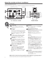 4
4
-
 5
5
-
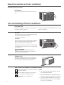 6
6
-
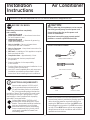 7
7
-
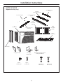 8
8
-
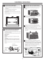 9
9
-
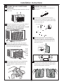 10
10
-
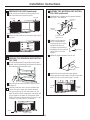 11
11
-
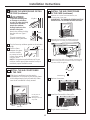 12
12
-
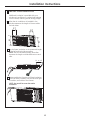 13
13
-
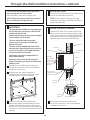 14
14
-
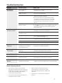 15
15
-
 16
16
-
 17
17
-
 18
18
-
 19
19
-
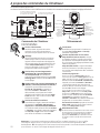 20
20
-
 21
21
-
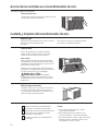 22
22
-
 23
23
-
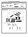 24
24
-
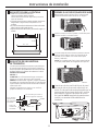 25
25
-
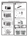 26
26
-
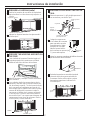 27
27
-
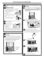 28
28
-
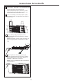 29
29
-
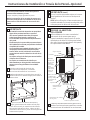 30
30
-
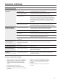 31
31
-
 32
32
-
 33
33
-
 34
34
-
 35
35
-
 36
36


GE AEH24DT El manual del propietario
- Tipo
- El manual del propietario
- Este manual también es adecuado para
en otros idiomas
- français: GE AEH24DT Le manuel du propriétaire
- English: GE AEH24DT Owner's manual