PPA Controladora 1 Ponto Manual de usuario
- Tipo
- Manual de usuario

USER MANUAL
CONTROLADORA IP- FLEX
1 TWO-WAY POINT
P30575 - 07/2022
Rev. 0
LINE
Made by: Motoppar da Amazônia Indústria e Comércio de Eletrônicos LTDA
Praça Linear, 100, Bloco 2 - Centro
Santa Rita do Sapucaí - MG - CEP 37.540-000 - Brasil
CNPJ: 09.084.119/0002-45
www.citrox.com.br | +55 14 3407 1000
INTRODUCTION
Easy to install, the controladora has the following features:
- TCP/IP communication.
- Online and offline working mode
- Stores 8000 thousand users (card or password) in memory. In online mode
there is no user limit.
- Stores 10 thousand events in off-line mode. In online mode are unlimited.
- Compatible with 26-bit Wiegand readers.
- Configuration of the relay time.
- Anti-passback.
The Controladora was developed to attend installations where it is necessary
to control only one input/output, or two points with only input control,
releasing the output through a pushbutton.
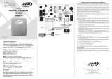
TECHNICAL CHARACTERISTICS:
Power
Consume max without readers
Readers input
Sensor input*
Pushbutton input
Relay output
Alarm relay output / auxiliary output*
2 point mode:
The sensor will become a pushbutton for point 2.
Relay 1 referred to point 1 and auxiliary relay referred to point 2.
WARNING
1- The controladora must be powered by a stabilized 12V source, the source
voltage cannot vary. The source must be compatible with its power. Voltage
higher than specified may damage the equipment.
2- Never install this equipment in structures that spread flames.
3 - This product must be housed in an airtight box and protected from sun,
rain and humidity. Install it in an inconspicuous, easily accessible location for
future configuration or hardware maintenance.
4 - This equipment must only be installed by a specialized technician.
5 - In case of doubt, consult our technical department.
Controladora name: IP-FLEX 1 standard
User: Adm
Password: adm
12V source - Power input.
12V output - 12V output for power supply.
LED indication
- When there is a valid access, the LED lights up, optional.
Sensor input
- Allows the installation of dry contact sensors or NPN or PNP output.
Pushbutton input
- Install dry contact pushbutton contact NA (normally open).
Reader input 1
- Install 26bit wiegand readers, compatible with the majority of readers
on the market.
Reader input 2
- Install 26bit wiegand readers, compatible with the majority of readers
on the market.
Reset
- The reset button deletes all memory data, such as: settings, username,
passwords. To reset, turn on the controladora with the reset button
pressed, when LED2 lights up, release the button.
Network input
- Input for Rj45 connector. Communication of the controladora with the
computer through a local network or point to point to use point to point
use a crossover cable, and to connect it to the network use a straight
cable
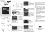
Sensor connection NPN Sensor coneection PNP
CLOSE NPN JUMPER OPEN PNP JUMPER
LED connection indications
12V output
The LED connection diagram is
the same for all LEDs.
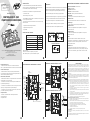
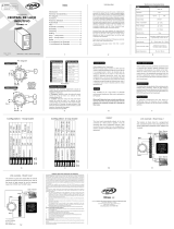
DESCRIPTION OF INTERNAL PARTS AND BOARD CONNECTION
12V source input
- 12V power supply, use with P4 connector sources.
Note: If you are already using a font in the terminal, do not use this entry.
Relay contacts points
- Dry contact output COM (common) NA (normally open) NF (normally
closed), used to activate devices such as: electromagnetic locks,
barriers, etc...
Alarm relay / Auxiliary output
- Dry contact relay output. It can be used as an open door burglar alarm,
or as an auxiliary point.
- If selected as alarm, it will be triggered based on sensor input.
0 times can be set.
- If selected as auxiliary output, the relay will be activated together with
the point's relay. and the activation time can be set.
- If it is selected as robbery, when entering without having access, the
relay is activated, and it will be activated according to the configured time.
Sensor jumper
- Selects whether the sensor input will be of the NPN or PNP type.
NPN closed jumper.
PNP open jumper.
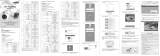
INTERNAL PARTS AND CONNECTIONS OF THE BOARD
Sensor
jumper
12V source
12V output
LED indication
Input
Sensor
Input
Pushbutton
Reader
Input 1
Reader
input 2
Restart 12V source input
Network input
Relay
Contacts point
Relay
Alarm/auxiliary output
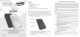
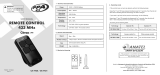
SENSOR
PUSHBUTTON
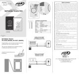
CONNECTION DIAGRAM: 1 MODULE POINT
INPUT
READER
+ Red
OUTPUT
READER
- Black
Green
White
+ Red
- Black
Green
White
SOURCE
SOURCE
SOURCE
SOURCE
SOURCE
SOURCE
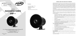
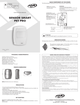
CONNECTION DIAGRAM: 2 MODULE POINT
PUSHBUTTON
POINT 2
PUSHBUTTON
POINT 1
READER
POINT 1
READER
POINT 2
+ Red
- Black
Green
White
+ Red
- Black
Green
White
Lock point 1
Lock point 2
WARNING:
Do not use the equipment
without referring to this
manual rst.
GENERAL TERMS AND CONDITIONS OF WARRANTY
MOTOPPAR da Amazônia Indústria e Comércio de Eletrônicos Ltda, registered with CNPJ No.
09.084.119/0002-45, located at Praça Linear, No. 100, Bloco II, Centro, Santa Rita do
Sapucaí/MG, CEP 37.500-000, manufacturer of the PPA and CITROX products, guarantees this
device against defects in design, manufacture, assembly and/or jointly and severally as a result
of defects in the quality of the material that make it inappropriate or unsuitable for the
consumption for which it is intended, for a legal period of 90 (ninety) days from the date of
purchase, provided that the installation guidelines described in the instruction manual are
observed.
As a result of the credibility and trust placed in PPA AND CITROX products, we added another
275 days to the above period, reaching a total of 1 (one) year, also counted from the date of
purchase to be proven by the consumer through the proof of purchase (Supervisor Note).
In the event of a defect, within the warranty period, the liability of PPA and/or CITROX is
restricted to the repair or replacement of the device manufactured by it, under the following
conditions:
1. The repair and readjustment of the equipment can only be carried out by the Technical
Assistance, which is qualied to open, remove, replace parts or components, as well as
repair the defects covered by the warranty, and, in the absence of this and any use of
parts not originals contained in the use, will result in the waiver of this term by the
consumer;
2. The warranty will not extend to accessories such as cables, screws kit, xing brackets,
sources, etc.;
3. Expenses for packaging, transport and reinstallation of the product are exclusively
borne by the consumer;
4. The equipment must be sent directly to the company responsible for the sale,
representative of the manufacturer, through the address on the purchase invoice,
properly packaged, thus avoiding the loss of warranty;
5. The replacement or repair of the equipment does not extend the warranty period.
This warranty will be void if the product:
1. Suffer damages caused by agents of nature, such as atmospheric discharges, oods,
res, landslides, etc.;
2. It is installed in an improper electrical network or even in disagreement with any of the
installation instructions set out in the manual;
3. Defects caused by falls, blows or any other physical accident;
4. For violation of the equipment or attempt to repair by unauthorized personnel;
5. It is not used for its intended purpose;
6. Not used under normal conditions;
7. Suffer damage caused by accessories or equipment attached to the product.
Recommendation:
We recommend the installation and maintenance of the product by a specialized technical
service.
If the product has a defect or abnormal operation, look for a specialized Technical Service for
the necessary corrections.

MANUAL DE USUARIO
CONTROLADOR IP- FLEX
1 PUNTO DE DOS DIRECCIONES
P30575 - 07/2022
Rev. 0
LÍNEA
Fabricado por: Motoppar da Amazônia Indústria e Comércio de Eletrônicos LTDA
Praça Linear, 100, Bloco 2 - Centro
Santa Rita do Sapucaí - MG - CEP 37.540-000 - Brasil
CNPJ: 09.084.119/0002-45
www.citrox.com.br | +55 14 3407 1000
ATENCIÓN:
No utilice el equipo sin
antes leer el manual de
instrucciones.
INTRODUCCIÓN
Fácil de instalar, el controlador tiene las siguientes características:
- Comunicación TCP/IP.
- Modo de trabajo on-line y off-line
- Almacena 8000 mil usuarios (tarjeta o contraseña) en memoria. En modo
on-line no hay límite de usuarios.
- Almacena 10 mil eventos en modo off-line. En el modo en línea no hay
límites de eventos.
- Compatible con lectores wiegand de 26 bits.
- Configuración del tiempo de relé.
- Anti-passback.
El Controlador fue desarrollado para atender instalaciones donde es
necesario controlar solo una entrada/salida, o dos puntos con control
solo de entrada, liberando la salida a través de ojal.
CARACTERISTICAS TECNICAS:
Alimentación
Consumir máximo sin lectores
Entrada para lectores
Entrada para sensores*
Entrada al ojal
Salida de relé
Salida de relé de alarma / salida auxiliar*
Modo de 2 puntos:
El sensor se convertirá en un pulsador para el punto 2.
Relé 1 referido al punto 1 y relé auxiliar referido al punto 2.
ADVERTENCIA
1- El controlador debe ser alimentado con una fuente de 12V estabilizada, el
voltaje de la fuente no puede variar. La fuente debe ser compatible con
su potencia. Un voltaje superior al especificado puede dañar el equipo.
2- Nunca instale este equipo en estructuras que propaguen llamas.
3 - Este producto debe estar alojado en una caja hermética y protegido del
sol, la lluvia y la humedad. Instálelo en una ubicación discreta y de fácil
acceso para futuras configuraciones o mantenimiento de hardware.
4 - Este equipo sólo debe ser instalado por un técnico especializado.
5 - En caso de duda, consulte con nuestro departamento técnico.
Nombre del controlador: estándar IP-FLEX 1
Usuario: administrador
Contraseña: administrador
Fuente 12V - Entrada de alimentación.
Salida 12V - Salida 12V para fuente de alimentación.
Indicación LED
- Cuando hay un acceso válido, se enciende el LED, opcional.
Entrada de sensor
- Permite instalar sensores de contacto seco o salida NPN o PNP.
Entrada de ojal
- Instalar pulsador contacto seco NA (normalmente abierto).
Entrada del lector 1
- Instalar lectores wiegand de 26bit, compatibles con la mayoría de
lectores del mercado.
Entrada del lector 2
- Instalar lectores wiegand de 26bit, compatibles con la mayoría de
lectores del mercado.
Reset
- El botón de reset borra todos los datos de la memoria, como:
configuraciones, nombre de usuario, contraseñas. Para reiniciar, encienda
el controlador con el botón de reset presionado, cuando el LED2 se
encienda, suelte el botón.
Entrada de red
- Entrada para conector Rj45. Comunicación del controlador con la
computadora a través de una red local o punto a punto para usar punto
a punto use un cable cruzado, y para conectarlo a la red use un cable
recto
Conexión de sensor NPN Conexión de sensor NPN
JUMPER CERRADO NPN JUMPER ABIERTO PNP
Indicaciones de conexión LED
Salida de 12V
El diagrama de conexión del LED es
el mismo para todos los LED.
DESCRIPCIÓN DE PARTES INTERNAS Y CONEXIÓN DE LA CENTRAL
Entrada de fuente de 12 V
- Fuente de alimentación de 12V, uso con fuentes de conector P4.
Nota: si ya está utilizando una fuente en el terminal, no utilice esta entrada.
Contactos de relé de punto
- Salida de contacto seco COM (común) NA (normalmente abierto)
NF (normalmente cerrado), utilizado para activar dispositivos tales como:
cerraduras electromagnéticas, barreras, etc...
Relé de alarma / Salida auxiliar
- Salida de relé de contacto seco. Se puede utilizar como alarma antirrobo
de puerta abierta, o como punto auxiliar.
- Si se selecciona como alarma, se activará según la entrada del sensor.
Se puede configurar 0 tiempos.
- Si se selecciona como salida auxiliar, el relé se activará junto con el relé
del punto. y el tiempo de activación se puede configurar.
- Si se selecciona como robo, al entrar sin tener acceso, el relé se activa,
y se activará según el tiempo configurado.
Jumper de sensores
- Selecciona si la entrada del sensor será del tipo NPN o PNP.
Jumper cerrado NPN.
Jumper abierto PNP.
PARTES INTERNAS Y CONEXIONES DE LA CENTRAL
Jumper
de sensores
Fuente 12V
Salida 12V
Indicación LED
Entrada
Sensor
Aporte
Ojal
Lector
Entrada 1
Lector
Entrada 2
Reiniciar Entrada de fuente 12 V
Entrada de red
Contactos de
Relé de punto
Relé
Alarma/salida auxiliar
SENSOR
OJAL
ESQUEMA DE CONEXIÓN: MÓDULO 1 PUNTO
LECTOR
ENTRADA
+ Rojo
LECTOR
SALIDA
- Negro
Verde
Blanco
+ Rojo
- Negro
Verde
Blanco
FUENTE
FUENTE
FUENTE
FUENTE
FUENTE
FUENTE
ESQUEMA DE CONEXIÓN: MÓDULO 2 PUNTO
OJAL
PUNTO 2
OJAL
PUNTO 1
LECTOR
PUNTO 1
LECTOR
PUNTO 2
+ Rojo
- Negro
Verde
Blanco
+ Rojo
- Negro
Verde
Blanco
Cerradura punto 1
Cerradura punto 2
PLAZO DE GARANTÍA
MOTOPPAR da Amazônia Indústria e Comércio de Eletrônicos Ltda, registrada en el CNPJ nº
09.084.119/0002-45, con domicilio en Praça Linear, nº 100, Bloco II, Centro, Santa Rita do
Sapucaí/MG, CEP 37.500-000, fabricante de los productos PPA y CITROX, garantiza este
dispositivo contra defectos de diseño, fabricación, montaje y/o solidariamente como
consecuencia de defectos en la calidad del material que lo hagan inadecuado o inadecuado
para el consumo al que está destinado, por un plazo legal de 90 (noventa) días a partir de la
fecha de compra, siempre que se observen las pautas de instalación descritas en el manual de
instrucciones.
Como resultado de la credibilidad y conanza depositada en los productos PPA Y CITROX,
agregamos otros 275 días al período anterior, alcanzando un total de 1 (un) año, también
contados a partir de la fecha de compra para ser comprobada por el consumidor a través de la
comprobante de compra (Nota Supervisor).
En caso de defecto, dentro del período de garantía, la responsabilidad de PPA y/o CITROX se
limita a la reparación o sustitución del aparato por ella fabricado, en las siguientes condiciones:
1. La reparación y reajuste del equipo sólo podrá ser realizada por la Asistencia Técnica, la
cual está habilitada para abrir, remover, reponer piezas o componentes, así como
reparar los defectos cubiertos por la garantía, y, en defecto de esta y cualquier uso de
partes no originales contenidas en el uso, dará lugar a la renuncia a este término por
parte del consumidor;
2. La garantía no se extenderá a accesorios tales como cables, juego de tornillería,
soportes de jación, fuentes, etc.;
3. Los gastos de embalaje, transporte y reinstalación del producto corren exclusivamente
a cargo del consumidor;
4. El equipo debe ser enviado directamente a la empresa responsable de la venta,
representante del fabricante, a través de la dirección que gura en la factura de compra,
debidamente embalado, evitando así la pérdida de la garantía;
5. La sustitución o reparación del equipo no amplía el plazo de garantía.
Esta garantía quedará anulada si el producto:
1. Sufrir daños causados por agentes de la naturaleza, tales como descargas atmosféricas,
inundaciones, incendios, derrumbes, etc.;
2. Está instalado en una red eléctrica inadecuada o incluso en desacuerdo con cualquiera
de las instrucciones de instalación establecidas en el manual;
3. Defectos causados por caídas, golpes o cualquier otro accidente físico;
4. Por violación del equipo o intento de reparación por personal no autorizado;
5. No se utiliza para el n previsto;
6. No utilizado en condiciones normales;
7. Sufrir daños causados por accesorios o equipos acoplados al producto.
Recomendación:
Recomendamos la instalación y mantenimiento del producto por un servicio técnico
especializado.
Si el producto presenta algún defecto o funcionamiento anómalo, busque un Servicio Técnico
especializado para las correcciones necesarias.
-
 1
1
-
 2
2


PPA Controladora 1 Ponto Manual de usuario
- Tipo
- Manual de usuario
en otros idiomas
- English: PPA Controladora 1 Ponto User manual
Artículos relacionados
-
 PPA SS 400T Manual de usuario
-
 PPA Touch Push-Button Manual de usuario
-
 PPA Access Control System BIO3 Stand Alone Manual de usuario
-
 PPA ULTRA 22K SMART ON Manual de usuario
-
 PPA Dome IP 5MP Camara Manual de usuario
-
 PPA TX Slim Manual de usuario
-
 PPA Magnetic Siren Manual de usuario
-
 PPA Inductive Loop Control Board Manual de usuario
-
 PPA TX Dual Gate Manual de usuario
-
 PPA Smart Pet Pro Manual de usuario


