Kichler Lighting 43952NI Manual de usuario
- Tipo
- Manual de usuario

Date Issued: 10/13/17 IS-43952-US
We’re here to help 866-558-5706
Hrs: M-F 9am to 5pm EST
CAUTION – RISK OF SHOCK –
Disconnect Power at the main circuit breaker panel or main
fusebox before starting and during the installation.
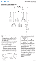
NOTE: Height of xture must be adjusted before xture is mounted
to ceiling.
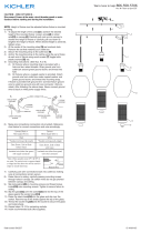
1) To adjust the length of the cord[1] to achieve the desired height
of the mounted xture: Loosen screw[2] on strain relief[3] on
canopy[4]. Carefully pull cord up into canopy to shorten the
height of xture or carefully pull cord down to lengthen the
height of xture. When desired height is achieved, tighten
screw. Repeat as required.
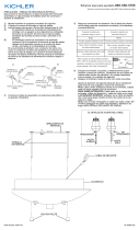
2) Find the appropriate threaded holes on mounting strap[5].
Assemble mounting screws[6] into threaded holes.
3) Attach mounting strap to outlet box[7] using the mounting strap
screws[8]. Mounting strap can be adjusted to suit position of
xture.
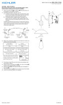
4) Grounding instructions: (See Illus. A or B).
A) On xtures where mounting strap is provided with a
hole and two raised dimples. Wrap ground wire from
outlet box around green ground screw, and thread into
hole.
B) On xtures where a cupped washer is provided. Attach
ground wire from outlet box under cupped washer and
green ground screw, and thread into mounting strap.
If xture is provided with ground wire. Connect xture ground
wire to outlet box ground wire with wire connector. After fol-
lowing the above steps. Never connect ground wire to black or
white power supply wires.
5) Make wire connections. Reference chart below for correct con-
nections and wire accordingly.
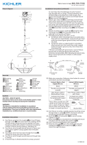
6) Raise xture[4] to ceiling, carefully passing mounting screws
through holes in canopy. Be certain wires do not get pinched
between canopy and ceiling.
7) Slip lockwashers[9] on mounting screws and thread lockup
knobs[10] onto mounting screws. Tighten to secure xture to
ceiling.
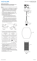
8) Slide the trim[14] and the glass shade[11] above the glass
shade/socket holder.
9) Insert the slotted metal washer[13] and the slotted rubber
washer[12] into the slot above the socket.
10) Insert recommended bulb (Not supplied).
11) Slide the glass shade back down with the trim on to the in-
stalled washers.
GREEN GROUND
SCREW
CUPPED
WASHER
OUTLET BOX
GROUND
FIXTURE
GROUND
DIMPLES
WIRE CONNECTOR
OUTLET BOX
GROUND
GREEN GROUND
SCREW
FIXTURE
GROUND
A
B
9
10
4
6
5
8
7
1
2
3
11
14
12
13
Connect Black or Red
Supply Wire to:
Connect White Supply Wire to:
Blac
kW
hite
*Parallel cord (round & smooth)
*Parallel cord (square & ridged)
Clear, Brown, Gold or Black
without Tracer
Clear, Brown, Gold or Black
with Tracer
Insulated wire (other than green)
with copper conductor
Insulated wire (other than green)
with silver conductor
*Note: When parallel wire (SPT I & SPT II)
are used. The neutral wire is square shaped or
ridged and the other wire will be round in
shape or smooth (see illus.)
Neutral Wire

Date Issued: 10/1317 IS-43952-US
Estamos aquí para ayudarle 866-558-5706
Horario: Lunes-Viernes 9am a 5pm EST (hora ocial del este)
NOTA: La altura de la luminaria debe ajustarse antes de mon
tar la techo.
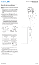
1) Para ajustar la longitud del cable[1] para alcanzar la altura
deseada del accesorio montado: Afloje el tornillo[2] en el alivio
de tensión[3] en el dosel[4]. Con cuidado, tire del cable hacia
arriba en el dosel para acortar la altura del aparato o tire con
cuidado del cable para alargar la altura del aparato. Cuando se
alcance la altura deseada, apriete el tornillo. Repita según sea
necesario.
2) Encuentre los oricios roscados adecuados en la correa de
montaje[5]. Montar los tornillos de montaje[6] en los oricios
roscados.
3) Fije la correa de montaje a la caja de salida[7]. La correa de
montaje se puede ajustar para adaptarse a la posición del
aparato.
4) Instrucciones para poner a tierra: (Ver Ilustraciones A o B).
A) En artefactos donde se suministra la abrazadera de
montaje con un agujero y dos depresiones onduladas.
Envuelva el conductor de tierra de la caja de salida
alrededor del tornillo de tierra verde y atornille en el
agujero.
B) En artefactos donde se suministra una arandela
cóncava. Fije el conductor de tierra de la caja de salida
debajo de la arandela cóncava y el tornillo de tierra
verde y enrosque en la abrazadera de montaje.
Si se suministra el artefacto con conductor de tierra. Conecte
el conductor de tierra del artefacto al conductor de tierra de
la caja de salida con conector de tierra después de seguir los
pasos anteriores. Nunca conecte el conductor de tierra a los
alambres de alimentación eléctrica negros o blancos.
5) Haga las conexiones de los alambres. Re érase a la tabla de
abajo para realizar las conexiones correctas de los cables.
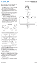
6) Levante la jación[4] al techo, pasando cuidadosamente
los tornillos de montaje a través de agujeros en el dosel.
Asegúrese de que todos los cables estén dentro del dosel y no
pellizcado entre el dosel y el techo.
7) Deslice las arandelas de seguridad[9] en los tornillos de
montaje y la rosca bloquee los mandos[10] en los tornillos de
montaje. Apriete para jar el accesorio a techo.
8) Deslice el adorno[14] y la pantalla de cristal[11] por encima del
portalámparas / portalámparas.
9) Inserte la arandela metálica ranurada[13] y la arandela de
goma ranurada[12] en la ranura situada encima del zócalo.
10) Inserte la bombilla recomendada (no incluido).
11) Deslice la pantalla de cristal hacia abajo con el borde en las
arandelas instaladas.
ARANDELA
CONCAVA
TIERRA DE LA
CAJA DE SALIDA
TORNILLO DE TIERRA,
VERDE
DEPRESIONES
TIERRA
ARTEFACTO
CONECTOR DE ALAMBRE
TIERRA DE LA
CAJA DE SALIDA
TORNILLO DE TIERRA,
VERDE
TIERRA
ARTEFACTO
A
B
PRECAUCIÓN – RIESGO DE DESCARGA ELÉCTRICA –
Desconecte la electricidad en el panel principal del interruptor
automático o caja principal de fusibles antes de comenzar y
durante la instalación.
Conectar el alambre de
suministro negro o rojo al
Conectar el alambre de
suministro blanco al
Negro Blanco
*Cordon paralelo (redondo y liso)
*Cordon paralelo (cuadrado y
estriado)
Claro, marrón, amarillio o negro
sin hebra identificadora
Claro, marrón, amarillio o negro
con hebra identificadora
Alambre aislado (diferente del
verde) con conductor de cobre
Alambre aislado (diferente del
verde) con conductor de plata
*Nota: Cuando se utiliza alambre paralelo
(SPT I y SPT II). El alambre neutro es de forma
cuadrada o estriada y el otro alambre será de
forma redonda o lisa. (Vea la ilustracíón).
Hilo Neutral
9
10
4
6
5
8
7
1
2
3
11
14
12
13
-
 1
1
-
 2
2


Kichler Lighting 43952NI Manual de usuario
- Tipo
- Manual de usuario
en otros idiomas
- English: Kichler Lighting 43952NI User manual
Artículos relacionados
-
 Kichler Lighting 43950OZ Manual de usuario
-
 Kichler Lighting 45945OZ Manual de usuario
-
 Kichler Lighting 45944OZ Manual de usuario
-
 Kichler Lighting 42992OZLED Manual de usuario
-
 Kichler Lighting 44102AP Manual de usuario
-
 Kichler Lighting 44104AP Manual de usuario
-
 Kichler Lighting 49992GG Manual de usuario
-
 Kichler Lighting 44217CLP Manual de usuario
-
 Kichler Lighting 43692NI Manual de usuario
-
Kichler Lighting 44085NI Manual de usuario


