Yamaha DTX760K Manual de usuario
- Categoría
- Tambores musicales
- Tipo
- Manual de usuario
Este manual también es adecuado para

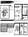
This manual describes the standard assembly procedure for the DTX760K/DTX920K electronic drum kits. It covers assembly and wiring of the kit as shown below.
When you have completed all of the steps described, you will be ready to turn on the drum trigger module and start playing.
Illustrations show the DTX700 drum trigger module.
ELECTRONIC DRUM KIT
DTX760K/DTX920K Assembly Manual
EN
• For assembly, you will require four individual packages – an RS700
Rack System, a DTP903 Pad Set, a DTP904 Pad Set, and a DTX700/
DTX900M Drum Trigger Module.
• This manual describes the process of assembling a drum-pad set and
drum trigger module to an already assembled RS700 Electronic Drum
Rack. Before starting the steps below, therefore, be sure to assemble
your RS700 as described in the Owner’s Manual that came with it.
Before starting assembly, lay a drum mat (sold separately) on the floor.
Alternatively, you can place cardboard from the drum kit packaging or the
like on the floor to prevent it from being scratched. This is particularly
important when using the HS740A Hi-hat Stand and KP100 Kick Pad.
IMPORTANT
NOTICE
Example of standard assembly
PCY155
(Cymbal Pad)
PCY135
(Cymbal Pad)
CH750
(Cymbal Holder)
RHH135
(Real Hi-hat Pad)
DTX700/DTX900M
Drum Trigger Module
HS740A
(Hi-hat Stand)
XP100T
(Tom Pad)
XP120SD
(Snare Pad)
SS662
(Snare Stand)
CH750
(Cymbal Holder)
PCY135
(Cymbal Pad)
CH755
(Cymbal Holder)
XP120T
(Tom Pad)
KP100
(Kick Pad)
RS700
(Rack System)
The purpose of the precautions detailed below is to ensure that this electronic drum kit can be used safely without fear of injury or property damage. As a means of indicating the severity and immediacy
of any risk of injury or property damage resulting from incorrect operation, these precautions are classified as either WARNING or CAUTION. The instructions displayed together with these precautions
are extremely important in terms of ensuring safety, and therefore, they should be fully observed.
* After reading this Assembly Manual, ensure that it is kept in a safe, convenient location for future reference.
* Be sure to also read the Assembly Manuals and/or Owner’s Manuals that came with your pads and rack.
NOTICE: Usage Precautions
• When connecting and disconnecting cables, be sure to hold the plug and not the cable itself. In addition,
avoid placing heavy items on top of cables and do not allow them to touch sharp edges. Failure to avoid
these precautions can lead to cable breakage and disconnection.
• Do not climb onto the electronic drum kit and avoid placing heavy objects on it. Failure to observe this pre-
caution can result in malfunction.
• Avoid using or storing the electronic drum kit in very hot locations (i.e., in direct sunlight, in close proximity to
a heater, or in a closed vehicle) or in highly humid locations (i.e., in a bathroom or outdoors in wet weather).
Failure to observe this precaution can lead to warping, discoloration, malfunction, or breakdown.
• Avoid cleaning the electronic drum kit with organic solvents, paint thinner, or alcohol as these substances
can cause warping and discoloration. Instead, we recommend you remove dust using a soft dry cloth or
wipe clean using a moist, tightly-wrung cloth. If the electronic drum kit is very dirty, first wipe the dirt away
using a cloth moistened with a neutral detergent solution and tightly wrung. Following this, wipe away the
detergent solution using a cloth soaked in water and tightly wrung.
Safety Precautions Please read carefully before proceeding.
Failure to observe the precautions described below can result in se-
rious injury or even death.
• Young children using this electronic drum kit should be supervised by a guardian to eliminate any
possibility of injury.
• Holders for cymbal and tom pads have sharp tips. In order to avoid injury, therefore, you should
take special care whenever handling these components.
• The anti-slip stoppers on kick pads and foot pedals have sharp tips. In order to avoid injury, there-
fore, you should take special care whenever handling these components.
• Be sure to securely tighten nuts and other fasteners when setting up this electronic drum kit. In
addition, be sure to proceed slowly when loosening nuts. If this precaution is not observed, pads
may fall off or the rack may collapse or fall over, possibly causing injury.
• Do not setup this electronic drum kit on a slope, on an unstable platform, or on any other unsafe
surface. If this precaution is not observed, it may topple over or fall, possibly causing injury.
• Whenever setting up this electronic drum kit, ensure that cables and the like are arranged safely. If
someone were to trip on a cable, the kit could topple over and cause injury.
• Under no circumstances should this electronic drum kit be disassembled or customized. Failure to
observe this precaution can result in injury or malfunction.
• Do not sit or stand on the rack. Doing so could cause it to fall over or break, possibly causing injury.
WARNING
Failure to observe the precautions described below can result in in-
jury and/or property damage.
• Mind your fingers when adjusting clamps. They can easily be crushed if care is not taken during
this operation.
• Be careful with the tips of supports, arms, screws, and the like. Fingers can easily be injured by
sharp tips if these components are not handled carefully.
• Do not place hands or feet under a kick pad or foot pedal. Doing so could result in injury.
• Do not use the electronic drum kit’s rack to hold acoustic drums. Doing so could cause clamps to
break and the drums to fall off, which in turn could lead to injury.
CAUTION
Manual Development Department
©2015 Yamaha Corporation
Published 10/2015 POTO*.*-**A0
Printed in Japan
ZT57980
Assemble the RS700 Electronic Drum Rack.
For instructions on how to assemble the RS700 Electronic Drum Rack, refer to the Owner’s Manual that came with it.
Open the boxes to reveal their contents.
Assemble the pads and the drum trigger module to the electronic drum rack.
1
2
Package 1: DTP903 Package 2: DTP904
PCY135
Cymbal Pad (x2)
PCY155
Cymbal Pad (x1)
RHH135
Real Hi-hat Pad (x1)
Stand base for the
RHH135 (x1)
CH750
Cymbal Holder (x2)
CH755
Cymbal Holder (x1)
HS740A
Hi-hat Stand (x1)
Hi-hat clutch for the
RHH135 (x1)
Cable band for the
RHH135 (x1)
Stoppers for the
PCY135 and
PCY155 (x3)
2.5m stereo phone cables (x4) 4m stereo phone cables (x6)
Felts for the
PCY135 and
PCY155 (x3)
Cable bands (x10) Tuning key (x1) KP100 Owner’s Manual (x1)
PCY100/PCY135/PCY155 Owner’s Manual (x1)
RHH135 Owner’s Manual (x1)
XP120SD
Snare Pad (x1)
XP100T
Tom Pad (x2)
XP120T
Tom Pad (x1)
Clamp bolts (x3)
KP100
Kick Pad (x1)
SS662
Snare Stand (x1)
XP100T/100SD/120T/120SD Owner’s Manual (x1)
Assembly Manual (this pamphlet)
Package 3: DTX700/DTX900M
DTX700/DTX900M
Drum Trigger Module (x1)
Module holder (x1) Module holder screw
(x4)
AC power adaptor* (x1)
* May not be included depending on your particular area.
Please check with your Yamaha dealer.
DTX700/DTX900M Owner’s Manual (x1)
DTX700/DTX900M Data List (x1)
3
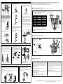
Assembling the cymbal holders Assembling the tom pads
1.
Assemble the cymbal holders (CH750 x 2, CH755 x 1) on the electronic
drum rack as shown below.
CH750
CH750
CH755
1.
Attach the clamp bolt to each of the tom pads and pro-
visionally tighten (by 5 or 6 turns).
2.
Push the tom pads onto the rack’s clamp rods. Ensure
that the rod section is fully inserted into the each pad’s
mounting hole, and then tighten the clamp bolt to se-
cure the pad in place.
3.
Loosen clamp bolts A to E as shown below to adjust
the height and angle of any of the pads. When correct-
ly positioned, be sure to securely retighten the bolts
before proceeding to the next step.
XP100T
XP120T
Tom pad (rear side)
Clamp bolt (tighten in the
direction of the arrow)
Tom pad
Rod section
Clamp rod
Insert
Clamp bolt
Clamp bolt B
Clamp bolt D
Clamp bolt E
Clamp bolt A
Clamp bolt C
* Specifications and descriptions in this owner’s manual are for information purposes only. Yamaha Corp. reserves the right to change or modify products or specifications at any time
without prior notice. Since specifications, equipment or options may not be the same in every locale, please check with your Yamaha dealer.
Continued on other side

Assembling the drum trigger module and cymbal pads
Assembling the drum trigger module
1.
Secure the module holder
to the bottom of the drum
trigger module using the
module holder screws.
2.
Push the module holder into the holder clamp and tighten the
clamp bolt to secure it in place.
Assembling the cymbal pads
1.
Using a tuning key, loosen the stopper’s key bolt.
2.
Remove the wing nut, the two felt pads, and the bolt cover
from the cymbal holder.
3.
Place the stopper on the cymbal holder.
* If the key bolt was not sufficiently loosened in Step 1
above, it may not be possible to pass the stopper over the
cymbal holder’s shaft. In such a case, loosen the key bolt
as much as possible without removing it.
4.
Replace the bolt cover.
* Turn the bolt cover to tighten it onto the threaded section
and firmly secure it in place.
5.
With the stopper making full contact with the bottom surface
of the bolt cover as shown below, tighten the stopper’s key
bolt using the tuning key.
6.
Place one of the felt pads removed in Step 2 on the cymbal
holder.
7.
Mount the pad on the cymbal stand. Lower the pad into place
with the cymbal holder’s shaft passing through the central
hole. When mounted, the stopper’s pin should rest inside the
pad’s smaller hole.
* If you were to play your cymbal pad without the stopper’s
pin positioned well inside the smaller hole, the pad could
rotate, causing the pin to be pulled out. It is very important,
therefore, to ensure that the stopper is secured as shown
in Step 5 above.
8.
Assemble the felt pad that came with the cymbal pad.
* The second felt pad removed from the cymbal holder in
Step 2 above is not required for assembly of your pad unit.
9.
Tighten the wing nut to secure the pad unit to the cymbal
holder.
A cymbal pad’s built-in sensor is located close to the Yamaha
logo found on the top surface. In order to achieve the best per-
formance from your pad, position it such that the area around
the logo can be easily struck. (See the figure above.)
PCY135
PCY155PCY135
Drum trigger module
Module holder
screws
Module holder
Drum trigger
module (back
side)
Front of module
Drum trigger module
+
module holder
Clamp bolt
Holder clamp
Insert
Key bolt
Tuning key
Stopper
Wing nut
Felt pads
Bolt cover
Cymbal holder
Bolt cover
Threaded section
Stopper
Cymbal holder
Bolt cover
Cymbal holder
Stopper
Full contact
Felt pad that came
with pad unit
Pad unit
Stopper’s pin
Felt pad
Smaller hole
Wing nut
Pin
Stopper
Cymbal holder
Pad unit
Bolt cover
Assembling the hi-hat stand
1.
If a drum mat (sold separately) is not available, lay a sheet of
cardboard on the floor to protect it from being scratched.
2.
Loosen the hi-hat stand’s wing bolt (a in the following figure).
3.
Open up the three legs as shown below and then retighten
the wing bolt a to lock them in place.
4.
Insert the footboard stabilizer rod into the frame hole as
shown below.
5.
As shown on the right, loosen the hi-hat clutch’s wing bolt b
and remove the hi-hat clutch.
* The hi-hat clutch is not required when assembling the
electronic drum kit in the standard fashion described in
this manual. Instead, the hi-hat clutch that came with the
RHH135 Real Hi-Hat Pad will be used.
6.
Remove the hi-hat shaft from the upper tube .
7.
Insert the hi-hat shaft from Step 6 as far as it will go into
the lower tube and screw in the tip.
8.
Insert the upper tube over the hi-hat shaft and tighten
the wing bolt c to secure it in place with the cymbal support
plate approximately half way between the top of the lower
tube and the top of the hi-hat shaft .
9.
Remove the felt pad and the support plate attached above
the cymbal support plate. It is not required when assembling
the electronic drum kit in the standard fashion described in
this manual.
10.
Assemble the RHH135 Real Hi-hat Pad.
* For detailed instructions, refer to the Setting Up section
in the RHH135 Owner’s Manual.
Wing bolt a
Footboard
stabilizer rod
Footboard
stabilizer rod
c
Felt washer
Support
plate
Cymbal
support plate
Hi-Hat clutch
Cymbal
support
plate
b
Assembling the kick pad
1.
If a drum mat (sold separately) is not available, lay a sheet of cardboard on the floor to protect it from being scratched.
2.
Remove the two wing bolts, spring washers, and flat washers from the kick pad frame, and line up each set nearby
in the order of removal.
3.
Join the base section to the frame as shown below, and then secure it in place by assembling the wing bolts, spring
washers, and flat washers removed in the previous step from the base side.
Frame
Frame
Base
Flat washerSpring washer
Wing bolt
Assembling the Snare Stand and Snare Pad
1.
Open up the snare stand’s legs and stand it up on the floor.
2.
Open up the snare stand’s basket section, lay the XP120SD Snare Pad on it,
adjust the basket, and then tighten the adjusting knob to secure the pad and
prevent it from moving.
Adjusting
knob
Legs
XP120SD
(Snare pad)
Basket
Arrange the hi-hat stand, the kick pad, and the snare stand as shown in Example of standard assembly on the other side of this sheet.
• Lay a drum mat (sold separately) on the floor underneath the hi-hat stand and the kick pad. Alternatively, you can place cardboard from the drum
kit packaging or the like on the floor to prevent it from being scratched.
• If the kick pad comes into contact with the electronic drum rack’s center strut, raise the center strut.
Connect the pads to the drum trigger module.
As described below, connect the output of each pad to the corresponding trigger input jack on the drum trigger module.
Connect the drum trigger module to a power supply.
Setting up the drum trigger module.
4
NOTICE
5
1.
As shown at right, connect the pads with the trigger input jacks (SNARE – KICK and HI-HAT CON-
TROL jack) of the drum trigger module by using the stereo phone cables.
• Insert the straight plugs of the cable into the trigger input jacks of the drum trigger module, then insert
the L-shaped plugs of the cables into each corresponding pad.
2.
In the case of snare and tom pads, wrap the cables around the cable clips to prevent them from being
pulled out.
Excessive bending can damage the pad cables. Ensure, therefore, that these ca-
bles are not bent at an extreme angle when wrapped around the clips.
Pads DTX700 jack names DTX900M jack names
SNARE q SNARE q SNARE
TOM1 w TOM1 w TOM1
TOM2 e TOM2 e TOM2
TOM3 r TOM3 r TOM3 or t TOM4
RIDE t RIDE y RIDE
CRASH y CRASH1 u CRASH1
CRASH2 u CRASH2 i CRASH2
HI HAT i HI HAT o HI HAT
HH CON HI-HAT CONTROL HI-HAT CONTROL
KICK o KICK/!0 !0 KICK/!1
NOTICE
HH CON
TOM2
TOM3
KICK
TOM1
RIDE
SNARE
CRASH
HI HAT
CRASH2
[Locations of pad jacks]
6
1.
Insert the power adaptor’s DC plug into the connector. Hook the power adaptor’s cord around
the cord clip to secure it in place.
2.
Using the cable bands, secure the cables to the electronic drum rack at the positions circled in the fig-
ure on the right. ( )
3.
Plug the AC power adaptor into an AC wall socket.
[Drum trigger module’s rear panel]
Cord clip
connector
7
[For DTX760K Owners]
Select the “DTX760K” trigger setup on the DTX700 drum trigger module. (For details on the trigger
setup procedure, see “Selecting a Sensitivity for the Entire Kit” from the DTX700 Owner’s Manual.)
If “DTX760K” is not displayed on the selection screen, please upgrade your DTX700’s firmware ver-
sion. Visit the following web page for information on the latest DTX700 firmware version and to
download firmware version upgrades.
http://download.yamaha.com/
If you would prefer not to upgrade your firmware version, select the “DTX750K” trigger setup, and
then make the following adjustments.
• Kick pad output (LEVEL) adjustment:
Adjust the trigger output to your desired setting by using the KP100 kick pad’s level adjustment
knob. For details, see “Adjusting the Output Level” from the KP100 Owner’s Manual.
• Pad type change for tom pads 1 to 3:
Select “XP120/100 Tom” as the DTX700 pad type. For details, refer to “For pad-related trigger set-
tings (TRIGGER/PAD/PAD TYPE 1/6)” from the DTX700 Reference Manual (pdf).
[For DTX920K Owners]
Select the “DTX920K” trigger setup on the DTX900M drum trigger module. (For details on the trigger
setup procedure, see “Selecting the Trigger Setup” from the DTX900M Owner’s Manual.)
If “DTX920K” is not displayed on the selection screen, please upgrade your DTX900M’s firmware
version. Visit the following web page for information on the latest DTX900M firmware version and
to download firmware version upgrades.
http://download.yamaha.com/
If you would prefer not to upgrade your firmware version, select the “DTX950K/900K” trigger setup,
and then make the following adjustment.
• Kick pad output (LEVEL) adjustment:
Adjust the trigger output to your desired setting by using the KP100 kick pad’s level adjustment
knob. For details, see “Adjusting the Output Level” from the KP100 Owner’s Manual.
Your electronic drum kit is now ready. * For instructions on turning on the drum trigger module, producing sounds, and other subsequent steps,
please refer to the Owner’s Manual that came with the module.
Transcripción de documentos
Manual Development Department ©2015 Yamaha Corporation Published 10/2015 POTO*.*-**A0 Printed in Japan ELECTRONIC DRUM KIT DTX760K/DTX920K Assembly Manual EN IMPORTANT Example of standard assembly 2 Open the boxes to reveal their contents. For instructions on how to assemble the RS700 Electronic Drum Rack, refer to the Owner’s Manual that came with it. Package 1: DTP903 PCY135 Cymbal Pad (x2) Package 2: DTP904 PCY155 Cymbal Pad (x1) RHH135 Real Hi-hat Pad (x1) XP120SD Snare Pad (x1) Stand base for the RHH135 (x1) XP100T Tom Pad (x2) XP120T Tom Pad (x1) • For assembly, you will require four individual packages – an RS700 Rack System, a DTP903 Pad Set, a DTP904 Pad Set, and a DTX700/ DTX900M Drum Trigger Module. PCY155 (Cymbal Pad) CH750 (Cymbal Holder) RHH135 (Real Hi-hat Pad) Assemble the RS700 Electronic Drum Rack. ZT57980 This manual describes the standard assembly procedure for the DTX760K/DTX920K electronic drum kits. It covers assembly and wiring of the kit as shown below. When you have completed all of the steps described, you will be ready to turn on the drum trigger module and start playing. Illustrations show the DTX700 drum trigger module. PCY135 (Cymbal Pad) 1 • This manual describes the process of assembling a drum-pad set and drum trigger module to an already assembled RS700 Electronic Drum Rack. Before starting the steps below, therefore, be sure to assemble your RS700 as described in the Owner’s Manual that came with it. CH750 (Cymbal Holder) XP100T (Tom Pad) NOTICE DTX700/DTX900M Drum Trigger Module Hi-hat clutch for the RHH135 (x1) CH750 Cymbal Holder (x2) KP100 Kick Pad (x1) Clamp bolts (x3) SS662 Snare Stand (x1) Before starting assembly, lay a drum mat (sold separately) on the floor. Alternatively, you can place cardboard from the drum kit packaging or the like on the floor to prevent it from being scratched. This is particularly important when using the HS740A Hi-hat Stand and KP100 Kick Pad. PCY135 (Cymbal Pad) HS740A Hi-hat Stand (x1) CH755 Cymbal Holder (x1) Cable band for the RHH135 (x1) CH755 (Cymbal Holder) Stoppers for the PCY135 and PCY155 (x3) XP120T (Tom Pad) XP100T/100SD/120T/120SD Owner’s Manual (x1) Assembly Manual (this pamphlet) 2.5m stereo phone cables (x4) HS740A (Hi-hat Stand) XP120SD (Snare Pad) 4m stereo phone cables (x6) Package 3: DTX700/DTX900M RS700 (Rack System) KP100 (Kick Pad) Felts for the PCY135 and PCY155 (x3) DTX700/DTX900M Drum Trigger Module (x1) Module holder (x1) Module holder screw (x4) SS662 (Snare Stand) KP100 Owner’s Manual (x1) PCY100/PCY135/PCY155 Owner’s Manual (x1) RHH135 Owner’s Manual (x1) Tuning key (x1) Cable bands (x10) AC power adaptor* (x1) * May not be included depending on your particular area. Please check with your Yamaha dealer. DTX700/DTX900M Owner’s Manual (x1) DTX700/DTX900M Data List (x1) Safety Precautions Please read carefully before proceeding. The purpose of the precautions detailed below is to ensure that this electronic drum kit can be used safely without fear of injury or property damage. As a means of indicating the severity and immediacy of any risk of injury or property damage resulting from incorrect operation, these precautions are classified as either WARNING or CAUTION. The instructions displayed together with these precautions are extremely important in terms of ensuring safety, and therefore, they should be fully observed. * After reading this Assembly Manual, ensure that it is kept in a safe, convenient location for future reference. 3 Assemble the pads and the drum trigger module to the electronic drum rack. * Be sure to also read the Assembly Manuals and/or Owner’s Manuals that came with your pads and rack. Assembling the cymbal holders WARNING Failure to observe the precautions described below can result in serious injury or even death. CAUTION Failure to observe the precautions described below can result in injury and/or property damage. • Young children using this electronic drum kit should be supervised by a guardian to eliminate any possibility of injury. • Mind your fingers when adjusting clamps. They can easily be crushed if care is not taken during this operation. • Holders for cymbal and tom pads have sharp tips. In order to avoid injury, therefore, you should take special care whenever handling these components. • Be careful with the tips of supports, arms, screws, and the like. Fingers can easily be injured by sharp tips if these components are not handled carefully. • The anti-slip stoppers on kick pads and foot pedals have sharp tips. In order to avoid injury, therefore, you should take special care whenever handling these components. • Do not place hands or feet under a kick pad or foot pedal. Doing so could result in injury. • Be sure to securely tighten nuts and other fasteners when setting up this electronic drum kit. In addition, be sure to proceed slowly when loosening nuts. If this precaution is not observed, pads may fall off or the rack may collapse or fall over, possibly causing injury. • Do not setup this electronic drum kit on a slope, on an unstable platform, or on any other unsafe surface. If this precaution is not observed, it may topple over or fall, possibly causing injury. • Whenever setting up this electronic drum kit, ensure that cables and the like are arranged safely. If someone were to trip on a cable, the kit could topple over and cause injury. • Under no circumstances should this electronic drum kit be disassembled or customized. Failure to observe this precaution can result in injury or malfunction. • Do not sit or stand on the rack. Doing so could cause it to fall over or break, possibly causing injury. 1. Assembling the tom pads Assemble the cymbal holders (CH750 x 2, CH755 x 1) on the electronic drum rack as shown below. 2. Push the tom pads onto the rack’s clamp rods. Ensure XP100T that the rod section is fully inserted into the each pad’s mounting hole, and then tighten the clamp bolt to secure the pad in place. CH750 CH750 Tom pad CH755 Rod section • Do not use the electronic drum kit’s rack to hold acoustic drums. Doing so could cause clamps to break and the drums to fall off, which in turn could lead to injury. Clamp rod Insert Clamp bolt XP120T NOTICE: Usage Precautions • When connecting and disconnecting cables, be sure to hold the plug and not the cable itself. In addition, avoid placing heavy items on top of cables and do not allow them to touch sharp edges. Failure to avoid these precautions can lead to cable breakage and disconnection. • Do not climb onto the electronic drum kit and avoid placing heavy objects on it. Failure to observe this precaution can result in malfunction. • Avoid using or storing the electronic drum kit in very hot locations (i.e., in direct sunlight, in close proximity to a heater, or in a closed vehicle) or in highly humid locations (i.e., in a bathroom or outdoors in wet weather). Failure to observe this precaution can lead to warping, discoloration, malfunction, or breakdown. • Avoid cleaning the electronic drum kit with organic solvents, paint thinner, or alcohol as these substances can cause warping and discoloration. Instead, we recommend you remove dust using a soft dry cloth or wipe clean using a moist, tightly-wrung cloth. If the electronic drum kit is very dirty, first wipe the dirt away using a cloth moistened with a neutral detergent solution and tightly wrung. Following this, wipe away the detergent solution using a cloth soaked in water and tightly wrung. 3. Loosen clamp bolts A to E as shown below to adjust 1. Attach the clamp bolt to each of the tom pads and provisionally tighten (by 5 or 6 turns). the height and angle of any of the pads. When correctly positioned, be sure to securely retighten the bolts before proceeding to the next step. Clamp bolt B Clamp bolt (tighten in the direction of the arrow) Clamp bolt D Clamp bolt E Tom pad (rear side) Clamp bolt A Clamp bolt C * Specifications and descriptions in this owner’s manual are for information purposes only. Yamaha Corp. reserves the right to change or modify products or specifications at any time without prior notice. Since specifications, equipment or options may not be the same in every locale, please check with your Yamaha dealer. Continued on other side 4 Assembling the drum trigger module and cymbal pads Assembling the cymbal pads PCY135 PCY155 1. • Lay a drum mat (sold separately) on the floor underneath the hi-hat stand and the kick pad. Alternatively, you can place cardboard from the drum kit packaging or the like on the floor to prevent it from being scratched. NOTICE • If the kick pad comes into contact with the electronic drum rack’s center strut, raise the center strut. 5. With the stopper making full contact with the bottom surface Using a tuning key, loosen the stopper’s key bolt. of the bolt cover as shown below, tighten the stopper’s key bolt using the tuning key. Stopper Drum trigger module Arrange the hi-hat stand, the kick pad, and the snare stand as shown in Example of standard assembly on the other side of this sheet. 5 Key bolt PCY135 Bolt cover Connect the pads to the drum trigger module. As described below, connect the output of each pad to the corresponding trigger input jack on the drum trigger module. Full contact Tuning key Stopper 2. Remove the wing nut, the two felt pads, and the bolt cover 1. Cymbal holder A cymbal pad’s built-in sensor is located close to the Yamaha logo found on the top surface. In order to achieve the best performance from your pad, position it such that the area around the logo can be easily struck. (See the figure above.) 6. Place one of the felt pads removed in Step 2 on the cymbal holder. Felt pads 7. Bolt cover Assembling the drum trigger module 1. Secure the module holder to the bottom of the drum trigger module using the module holder screws. Module holder screws Cymbal holder Drum trigger module (back side) Pads * If the key bolt was not sufficiently loosened in Step 1 above, it may not be possible to pass the stopper over the cymbal holder’s shaft. In such a case, loosen the key bolt as much as possible without removing it. q SNARE q SNARE TOM1 w TOM1 w TOM1 TOM2 e TOM2 e TOM2 * If you were to play your cymbal pad without the stopper’s pin positioned well inside the smaller hole, the pad could rotate, causing the pin to be pulled out. It is very important, therefore, to ensure that the stopper is secured as shown in Step 5 above. TOM3 r TOM3 r TOM3 or t TOM4 RIDE t RIDE y RIDE CRASH y CRASH1 u CRASH1 CRASH2 u CRASH2 i CRASH2 HI HAT i HI HAT o HI HAT HH CON HI-HAT CONTROL HI-HAT CONTROL KICK o KICK/!0 !0 KICK/!1 9. Tighten the wing nut to secure the pad unit to the cymbal holder. 2. Push the module holder into the holder clamp and tighten the Felt pad that came with pad unit Bolt cover Pad unit Insert HI HAT HH CON TOM3 Excessive bending can damage the pad cables. Ensure, therefore, that these cables are not bent at an extreme angle when wrapped around the clips. SNARE TOM2 TOM1 KICK Pad unit 6 Felt pad Threaded section Clamp bolt RIDE Smaller hole Stopper Drum trigger module + module holder NOTICE Stopper’s pin clamp bolt to secure it in place. CRASH2 pulled out. 4. Replace the bolt cover. * Turn the bolt cover to tighten it onto the threaded section and firmly secure it in place. CRASH 2. In the case of snare and tom pads, wrap the cables around the cable clips to prevent them from being Wing nut Front of module DTX900M jack names SNARE * The second felt pad removed from the cymbal holder in Step 2 above is not required for assembly of your pad unit. 3. Place the stopper on the cymbal holder. DTX700 jack names Mount the pad on the cymbal stand. Lower the pad into place with the cymbal holder’s shaft passing through the central hole. When mounted, the stopper’s pin should rest inside the pad’s smaller hole. 8. Assemble the felt pad that came with the cymbal pad. Module holder [Locations of pad jacks] • Insert the straight plugs of the cable into the trigger input jacks of the drum trigger module, then insert the L-shaped plugs of the cables into each corresponding pad. from the cymbal holder. Wing nut As shown at right, connect the pads with the trigger input jacks (SNARE – KICK and HI-HAT CONTROL jack) of the drum trigger module by using the stereo phone cables. Bolt cover Connect the drum trigger module to a power supply. Pin 1. Cymbal holder Holder clamp Stopper Insert the power adaptor’s DC plug into the the cord clip to secure it in place. Cymbal holder [Drum trigger module’s rear panel] connector. Hook the power adaptor’s cord around Cord clip connector Assembling the hi-hat stand 1. If a drum mat (sold separately) is not available, lay a sheet of cardboard on the floor to protect it from being scratched. 2. Loosen the hi-hat stand’s wing bolt (a in the following figure). 3. Open up the three legs as shown below and then retighten the wing bolt a to lock them in place. 4. 5. As shown on the right, loosen the hi-hat clutch’s wing bolt b and remove the hi-hat clutch. Felt washer * The hi-hat clutch is not required when assembling the electronic drum kit in the standard fashion described in this manual. Instead, the hi-hat clutch that came with the RHH135 Real Hi-Hat Pad will be used. 6. Remove the hi-hat shaft 7. Insert the hi-hat shaft Insert the footboard stabilizer rod into the frame hole as shown below. Hi-Hat clutch the lower tube from the upper tube . from Step 6 as far as it will go into and screw in the tip. b Support plate Cymbal support plate Cymbal support plate c 2. Using the cable bands, secure the cables to the electronic drum rack at the positions circled in the figure on the right. ( ) 3. Plug the AC power adaptor into an AC wall socket. 8. Insert the upper tube Wing bolt a over the hi-hat shaft and tighten the wing bolt c to secure it in place with the cymbal support plate approximately half way between the top of the lower tube and the top of the hi-hat shaft . 9. Remove the felt pad and the support plate attached above 7 the cymbal support plate. It is not required when assembling the electronic drum kit in the standard fashion described in this manual. Footboard stabilizer rod Footboard stabilizer rod 10. Assemble the RHH135 Real Hi-hat Pad. * For detailed instructions, refer to the Setting Up section in the RHH135 Owner’s Manual. Assembling the kick pad Assembling the Snare Stand and Snare Pad 1. If a drum mat (sold separately) is not available, lay a sheet of cardboard on the floor to protect it from being scratched. 2. Remove the two wing bolts, spring washers, and flat washers from the kick pad frame, and line up each set nearby 1. Open up the snare stand’s legs and stand it up on the floor. 2. Open up the snare stand’s basket section, lay the XP120SD Snare Pad on it, in the order of removal. 3. Join the base section to the frame as shown below, and then secure it in place by assembling the wing bolts, spring washers, and flat washers removed in the previous step from the base side. Spring washer adjust the basket, and then tighten the adjusting knob to secure the pad and prevent it from moving. Basket [For DTX760K Owners] [For DTX920K Owners] Select the “DTX760K” trigger setup on the DTX700 drum trigger module. (For details on the trigger setup procedure, see “Selecting a Sensitivity for the Entire Kit” from the DTX700 Owner’s Manual.) If “DTX760K” is not displayed on the selection screen, please upgrade your DTX700’s firmware version. Visit the following web page for information on the latest DTX700 firmware version and to download firmware version upgrades. http://download.yamaha.com/ Select the “DTX920K” trigger setup on the DTX900M drum trigger module. (For details on the trigger setup procedure, see “Selecting the Trigger Setup” from the DTX900M Owner’s Manual.) If “DTX920K” is not displayed on the selection screen, please upgrade your DTX900M’s firmware version. Visit the following web page for information on the latest DTX900M firmware version and to download firmware version upgrades. http://download.yamaha.com/ If you would prefer not to upgrade your firmware version, select the “DTX750K” trigger setup, and then make the following adjustments. If you would prefer not to upgrade your firmware version, select the “DTX950K/900K” trigger setup, and then make the following adjustment. • Kick pad output (LEVEL) adjustment: Adjust the trigger output to your desired setting by using the KP100 kick pad’s level adjustment knob. For details, see “Adjusting the Output Level” from the KP100 Owner’s Manual. • Kick pad output (LEVEL) adjustment: Adjust the trigger output to your desired setting by using the KP100 kick pad’s level adjustment knob. For details, see “Adjusting the Output Level” from the KP100 Owner’s Manual. • Pad type change for tom pads 1 to 3: Select “XP120/100 Tom” as the DTX700 pad type. For details, refer to “For pad-related trigger settings (TRIGGER/PAD/PAD TYPE 1/6)” from the DTX700 Reference Manual (pdf). Flat washer Wing bolt Frame Legs Base Setting up the drum trigger module. Adjusting knob XP120SD (Snare pad) Frame Your electronic drum kit is now ready. * For instructions on turning on the drum trigger module, producing sounds, and other subsequent steps, please refer to the Owner’s Manual that came with the module.-
 1
1
-
 2
2


Yamaha DTX760K Manual de usuario
- Categoría
- Tambores musicales
- Tipo
- Manual de usuario
- Este manual también es adecuado para
en otros idiomas
- français: Yamaha DTX760K Manuel utilisateur
- italiano: Yamaha DTX760K Manuale utente
- English: Yamaha DTX760K User manual
- Deutsch: Yamaha DTX760K Benutzerhandbuch
- русский: Yamaha DTX760K Руководство пользователя
- Nederlands: Yamaha DTX760K Handleiding
- português: Yamaha DTX760K Manual do usuário
- dansk: Yamaha DTX760K Brugermanual
- polski: Yamaha DTX760K Instrukcja obsługi
- čeština: Yamaha DTX760K Uživatelský manuál
- svenska: Yamaha DTX760K Användarmanual
- Türkçe: Yamaha DTX760K Kullanım kılavuzu
- suomi: Yamaha DTX760K Ohjekirja
- română: Yamaha DTX760K Manual de utilizare
Artículos relacionados
-
Yamaha DTX750K Manual de usuario
-
-
Yamaha PCY135 El manual del propietario
-
-
-
Yamaha DTX6K Manual de usuario
-
-
-
-