Dell PowerEdge 750 Guía del usuario
- Categoría
- Accesorios de rack
- Tipo
- Guía del usuario

Rack Installation Guide
Guide d'installation du rack
Rack-Installationsanleitung
ラック取り付けガイド
Guía de instalación del rack


Rack Installation Guide

Notes, Notices, and Cautions
NOTE: A NOTE indicates important information that helps you make better use of your computer.
NOTICE: A NOTICE indicates either potential damage to hardware or loss of data and tells you how
to avoid the problem.
CAUTION: A CAUTION indicates a potential for property damage, personal injury, or death.
____________________
Information in this document is subject to change without notice.
© 2004 Dell Inc. All rights reserved.
Reproduction in any manner whatsoever without the written permission of Dell Inc. is strictly forbidden.
Trademarks used in this text: VersaRails, and RapidRails are trademarks of Dell Inc.;
Microsoft and Windows are registered trademarks of Microsoft Corporation.
Other trademarks and trade names may be used in this document to refer to either the entities claiming the marks
and names or their products. Dell Inc. disclaims any proprietary interest in trademarks and trade names other than its own.
August 2004 P/N M3505 Rev. A00

Contents 1-3
Contents
Safety Instructions. . . . . . . . . . . . . . . . . . . . . . . . . . . . 1-5
SAFETY: Rack Mounting of Systems
. . . . . . . . . . . . . . . . . 1-5
Installation Instructions
. . . . . . . . . . . . . . . . . . . . . . . . . 1-6
Before You Begin
. . . . . . . . . . . . . . . . . . . . . . . . . . 1-6
Important Safety Information
. . . . . . . . . . . . . . . . . . . . 1-6
Rack Requirements for VersaRails
. . . . . . . . . . . . . . . . . . 1-6
Four-Post Rack Installation
. . . . . . . . . . . . . . . . . . . . . . . . 1-7
Rack Stabilizer Feet
. . . . . . . . . . . . . . . . . . . . . . . . . 1-7
Recommended Tools and Supplies
. . . . . . . . . . . . . . . . . . 1-7
RapidRails Rack Kit Contents
. . . . . . . . . . . . . . . . . . . . 1-7
VersaRails Rack Kit Contents
. . . . . . . . . . . . . . . . . . . . 1-8
Installation Tasks
. . . . . . . . . . . . . . . . . . . . . . . . . . 1-8
Removing the Rack Doors
. . . . . . . . . . . . . . . . . . . . . . 1-9
Marking the Rack
. . . . . . . . . . . . . . . . . . . . . . . . . . 1-9
Installing the Mounting Rails in the Rack
. . . . . . . . . . . . . . . 1-11
Installing the System in the Rack
. . . . . . . . . . . . . . . . . . . 1-13
Installing the Releasable Tie Wraps
. . . . . . . . . . . . . . . . . 1-14
Removing the System From the Rack
. . . . . . . . . . . . . . . . . 1-15
Replacing the Rack Doors
. . . . . . . . . . . . . . . . . . . . . . 1-15
Two-Post Rack Installation
. . . . . . . . . . . . . . . . . . . . . . . . 1-15
Recommended Tools and Supplies
. . . . . . . . . . . . . . . . . . 1-15
Rack Kit Contents
. . . . . . . . . . . . . . . . . . . . . . . . . . 1-16
Installation Tasks
. . . . . . . . . . . . . . . . . . . . . . . . . . 1-16
Marking the Rack
. . . . . . . . . . . . . . . . . . . . . . . . . . 1-17
Installing the Mounting Rails
. . . . . . . . . . . . . . . . . . . . . 1-18
Installing the System in the Rack
. . . . . . . . . . . . . . . . . . . 1-22
Installing the Releasable Tie Wraps
. . . . . . . . . . . . . . . . . 1-22
Index . . . . . . . . . . . . . . . . . . . . . . . . . . . . . . . . . . 1-23

1-4 Contents
Figures
Figure 1-1. RapidRails Rack Kit Contents . . . . . . . . . . 1-7
Figure 1-2. VersaRails Rack Kit Contents
. . . . . . . . . . 1-8
Figure 1-3. One Rack Unit
. . . . . . . . . . . . . . . . . . 1-9
Figure 1-4. Marking the Vertical Rails
. . . . . . . . . . . . 1-10
Figure 1-5. Installing the RapidRails Mounting Rails
. . . . . 1-11
Figure 1-6. Installing the VersaRails Mounting Rails
. . . . . 1-12
Figure 1-7. Installing the System in the Rack
. . . . . . . . . 1-13
Figure 1-8. Installing the Releasable Tie Wraps
. . . . . . . 1-14
Figure 1-9. Two-Post Rack Kit Components
. . . . . . . . . 1-16
Figure 1-10. Two-Post, Open-Frame Relay Rack
Universal-Hole Spacing
. . . . . . . . . . . . . 1-17
Figure 1-11. Two-Post, Open-Frame Relay Rack
Wide-Hole Spacing
. . . . . . . . . . . . . . . 1-18
Figure 1-12. Installing the Mounting Rails
for Center-Mount Configuration
. . . . . . . . . 1-19
Figure 1-13. Configuring the Adjustable Mounting Bracket
for Flush-Mount Installation
. . . . . . . . . . . 1-20
Figure 1-14. Installing the Mounting Rails
for Flush-Mount Configuration
. . . . . . . . . . 1-21

Rack Installation Guide 1-5
Safety Instructions
Use the following safety guidelines to ensure your own personal safety and to help protect your
system and working environment from potential damage. For complete safety information,
see the
Product Information
Guide
.
SAFETY: Rack Mounting of Systems
Observe the following precautions for rack stability and safety.
Systems are considered to be components in a rack. Thus, "component" refers to any system as well
as to various peripherals or supporting hardware.
CAUTION: Installing systems in a rack without the front and side stabilizers installed could cause the
rack to tip over, potentially resulting in bodily injury under certain circumstances. Therefore, always
install the stabilizers before installing components in the rack.
CAUTION: After installing components in a rack, never pull more than one component out of the rack
on its slide assemblies at one time. The weight of more than one extended component could cause the
rack to tip over and injure someone.
NOTE: Your system is safety-certified as a free-standing unit and as a component for use in a rack
cabinet using the customer rack kit when both the rack cabinet and rack kit were designed for your
system. The installation of your system and rack kit in any other rack cabinet has not been approved by
any safety agencies. It is your responsibility to have the final combination of system and rack kit in a
cabinet evaluated for suitability by a certified safety agency. The manufacturer disclaims all warranties
and liability in connection with such combinations.
•
System rack kits are intended to be installed in an approved rack by trained service
technicians. If you install the kit in any other rack, be sure that the rack meets the
specifications.
• Before working on the rack, make sure that the stabilizers are secured to the rack, extended to
the floor, and that the full weight of the rack rests on the floor. Install front and side stabilizers
on a single rack or front stabilizers for joined multiple racks before working on the rack.
• Always load the rack from the bottom up, and load the heaviest item in the rack first.
• Make sure that the rack is level and stable before extending a component from the rack.
• Use caution when pressing the component rail release latches and sliding a component
into or out of a rack; the slide rails can pinch your fingers.
• After a component is inserted into the rack, carefully extend the rail into a locking position,
and then slide the component into the rack.
• Do not overload the AC power supply branch circuit that provides power to the rack.
The total rack load should not exceed 80 percent of the branch circuit rating.
• Ensure that proper airflow is provided to components in the rack.
• Do not step on or stand on any system/component when servicing other systems/components
in a rack.

1-6 Rack Installation Guide
Installation Instructions
This installation guide provides instructions for trained service technicians installing one or more
systems in an open-frame relay rack or in a rack cabinet. The RapidRails™ rack kit can be installed
in all the system manufacturer's rack cabinets without tools, and the VersaRails™ rack kit can be
installed in most industry-standard rack cabinets. The procedures for installing both RapidRails
and VersaRails rack kits are similar. One rack kit is required for each system to be installed in the
rack cabinet.
This guide includes procedures for the following rack kits:
• RapidRails kit in a four-post rack cabinet
• VersaRails kit in a four-post rack cabinet
• Two-post kit (installed in either center-mount or flush-mount configuration)
Before You Begin
Before you begin installing your system in the rack, carefully read "Safety Instructions," found
earlier in this guide, as well as the safety instructions found in your
Product Information Guide
for additional information.
CAUTION: When installing multiple systems in a rack, complete all of the procedures for the current
system before attempting to install the next system.
CAUTION: Rack cabinets can be extremely heavy and move easily on their casters. They do not have
brakes. Use extreme caution while moving the rack cabinet. Retract the leveling feet when relocating
the rack cabinet. Avoid long or steep inclines or ramps where loss of cabinet control may occur. Extend
the leveling feet for support and to prevent the cabinet from rolling.
NOTE: For instructions on installing the system itself, see "Installing the System in the Rack."
Important Safety Information
Observe the safety precautions in the following subsections when installing your system in the rack.
CAUTION: You must strictly follow the procedures in this document to protect yourself as well as
others who may be involved. Your system may be very large and heavy and proper preparation and
planning are important to prevent injury to yourself and to others. This precaution becomes
increasingly important when systems are installed high up in the rack.
CAUTION: Do not install rack kit components designed for another system. Use only the rack kit for
your system. Using the rack kit for another system may result in damage to the system and personal
injury to yourself and to others.
Rack Requirements for VersaRails
NOTICE: The VersaRails rack kit is intended to be installed by trained service technicians in a rack
that meets the specifications of American National Standards Institute (ANSI)/Electronic Industries
Association (EIA) standard ANSI/EIA-310-D-92, International Electrotechnical Commission (IEC) 297, and
Deutsche Industrie Norm (DIN) 41494. One rack kit is required for each system that is installed in a rack.

Rack Installation Guide 1-7
Four-Post Rack Installation
Before attempting this installation, read through this entire procedure carefully.
Rack Stabilizer Feet
CAUTION: Installing systems in a rack without the front and side stabilizer feet installed and anchored
to the floor could cause the rack to tip over, potentially resulting in bodily injury under certain
circumstances. Therefore, always install and anchor the stabilizer feet before installing components
in the rack.
The stabilizer feet help prevent the rack from tipping over. See the documentation provided
with the rack cabinet for instructions on installing and anchoring the stabilizer feet.
Recommended Tools and Supplies
You may need the following items to install the system in a four-post rack cabinet:
• #2 Phillips screwdriver
• Masking tape or a felt-tip pen, for use in marking the mounting holes to be used
RapidRails Rack Kit Contents
• One pair of RapidRails mounting rails
• Releasable tie wraps (2) (not shown in Figure 1-1)
Figure 1-1. RapidRails Rack Kit Contents
mounting rails (2)
releasable tie wrap attachment points (2)

1-8 Rack Installation Guide
VersaRails Rack Kit Contents
• One pair of VersaRails mounting rails
• 10-32 x 0.5-inch flange-head Phillips screws (8)
• Releasable tie wraps (2) (not shown in Figure 1-2)
NOTE: The nonmetric screws described in illustrations and in procedural steps are identified by size and
number of threads per inch. For example, a #10 Phillips-head screw with 32 threads per inch is identified
as a 10-32 screw.
Figure 1-2. VersaRails Rack Kit Contents
Installation Tasks
Installing a rack kit involves performing the following tasks (described in detail in subsequent
sections) in their numbered order:
1
Removing the rack doors
2
Marking the rack
3
Installing the mounting rails in the rack
• RapidRails installation
• VersaRails installation
10-32 x 0.5-inch
flange-head Phillips
screws (8)
mounting rails (2)
releasable tie wrap attachment points (2)

Rack Installation Guide 1-9
4
Installing the system in the rack
5
Routing cables
6
Replacing the rack doors
NOTE: Two procedures are provided for task 3. One procedure is for the RapidRails kit,
and one procedure is for the VersaRails kit.
Removing the Rack Doors
See the procedures for removing doors in the documentation provided with your rack cabinet.
CAUTION: Because of the size and weight of the rack cabinet doors, never attempt to remove or install
them by yourself.
CAUTION: Store the two doors where they will not injure someone if the doors accidently fall over.
Marking the Rack
For a 1-U system, you must allow 1 U (44 mm, or 1.75 inches) of vertical space for each system you
install in the rack.
Rack cabinets that meet EIA-310 standards have an alternating pattern of three holes per rack unit
with center-to-center hole spacing (beginning at the top hole of a 1-U space) of 15.9 mm, 15.9 mm,
and 12.7 mm (0.625 inch, 0.625 inch, and 0.5 inch) for the front and back vertical rails
(see Figure 1-3). Rack cabinets may have round or square holes.
NOTE: The vertical rails may be marked by horizontal lines and numbers in 1-U increments. If you want,
you can make a note of the number marking on the rack’s vertical rail. It is not necessary to mark or place
tape on the rack.
Figure 1-3. One Rack Unit
1 U (44 mm or 1.75 inches)
12.7 mm (0.5 inch)
15.9 mm (0.625 inch)
15.9 mm (0.625 inch)
12.7 mm (0.5 inch)

1-10 Rack Installation Guide
CAUTION: If you are installing more than one system, install the mounting rails so that the first system
is installed in the lowest available position in the rack.
To mark the rack, perform the following steps:
1
Place a mark (or tape) on the rack's front vertical rails where you want to locate the bottom
of the system you are installing in the rack.
The bottom of each 1-U space is at the middle of the narrowest metal area between holes
(marked with a horizontal line on some rack cabinets—see Figure 1-4).
2
Place a mark 44 mm (1.75 inches) above the original mark you made (or count up three holes
in a rack that meets EIA-310 standards) and mark the rack's front vertical rails with a felt-
tipped pen or masking tape (if you counted holes, place a mark just above the top hole). This
mark or piece of tape indicates where the system's upper edge will be located on the vertical
rails (see Figure 1-4).
Figure 1-4. Marking the Vertical Rails
tape on vertical rail

Rack Installation Guide 1-11
Installing the Mounting Rails in the Rack
Installing the RapidRails Mounting Rails
1
At the front of the rack cabinet, position one of the RapidRails mounting rails so that its
mounting-bracket flange fits between the marks or tape you placed (or numbered location)
on the vertical rails (see Figure 1-5).
The top mounting hook on the front mounting-bracket flange should enter the top hole
between the marks you made on the vertical rails.
2
Push the mounting rail forward until the mounting hooks enter their square holes, and then
push down on the mounting-bracket flange until the mounting hooks seat and the push
button pops out and clicks (see Figure 1-5).
3
At the back of the cabinet, pull back on the mounting-bracket flange until the mounting
hooks enter their square holes, and then push down on the flange until the mounting hooks
seat and the push button pops out and clicks.
4
Repeat step 1 through step 3 for the mounting rail on the other side of the rack.
5
Ensure that the mounting rails are mounted at the same vertical position on both sides
of the rack.
Figure 1-5. Installing the RapidRails Mounting Rails
front of rack
mounting rails (2)
mounting hooks (2)
push button

1-12 Rack Installation Guide
Installing the VersaRails Mounting Rails
1
At the front of the rack cabinet, position one of the VersaRails mounting rails so that its
mounting-bracket flange fits between the marks (or numbered location) on the vertical rails
(see Figure 1-6).
The three holes on the front of the mounting-bracket flange should align with the holes
between the marks you made on the front vertical rail.
2
Install two 10-32 x 0.5-inch flange-head Phillips screws in the mounting-bracket flange's top-
and bottom-holes to secure the mounting rail to the front vertical rail.
3
At the back of the cabinet, pull back on the mounting-bracket flange until the mounting
holes align with their respective holes on the back vertical rail.
4
Install two 10-32 x 0.5-inch flange-head Phillips screws in the back mounting-bracket flange's
top- and bottom-holes to secure the mounting rail to the back vertical rail.
5
Repeat step 1 through step 4 for the mounting rail on the other side of the rack.
6
Ensure that the mounting rails are mounted at the same position on the vertical rails on each
side of the rack.
Figure 1-6. Installing the VersaRails Mounting Rails
front of rack
mounting rails (2)
10-32 x 0.5-inch
flange-head Phillips
screws (4 per
mounting rail)
mounting-bracket flange

Rack Installation Guide 1-13
Installing the System in the Rack
CAUTION: If you are installing more than one system, install the first system in the lowest available
position in the rack.
1
Remove the optional system front bezel (if one is installed). See the procedures for removing
the bezel in the documentation provided with your system.
2
Place one hand on the front-bottom of the system and the other hand on the back-bottom
of the system.
3
Lift the system into position so that the side rails at the back of the system are aligned with
the mounting rails in the rack (see Figure 1-7).
CAUTION: Because of the size and weight of the system, never attempt to install the system in the
mounting rails by yourself.
Figure 1-7. Installing the System in the Rack
mounting
rails (2)
system rails (2)
thumbscrews (2)
release latches (2)

1-14 Rack Installation Guide
4
Push the system into the mounting rails until the system stops (see Figure 1-7).
5
Push in and turn the thumbscrews on each side of the front chassis panel to secure the system
to the rack.
6
Install the optional front bezel (if applicable). See the procedures for installing the bezel in
the documentation provided with your system.
NOTE: Figure 1-7 applies to the RapidRails, VersaRails, and two-post rack kits.
Installing the Releasable Tie Wraps
The two releasable tie wraps are used to secure your system’s cables to the mounting rails.
1
Locate the releasable tie wrap attachment points located on the two back mounting-bracket
flanges (see Figure 1-8).
2
Push the tie wrap’s fastener through the attachment point.
3
Push the tie wrap’s plunger until it snaps to secure the tie wrap to the mounting rail.
4
Using the releasable tie wrap, secure your system’s cables to the mounting rail.
Figure 1-8. Installing the Releasable Tie Wraps
mounting rails (2)
releasable tie wraps (2)

Rack Installation Guide 1-15
Removing the System From the Rack
To remove the system from the rack, perform the following procedure:
1
Remove the optional system front bezel (if one is installed). See the procedures
for removing the bezel in the documentation provided with your system.
2
Turn off the system and attached peripherals, and disconnect the system from the
electrical outlet.
3
Loosen the thumbscrews on each side of the front chassis panel that secures the system
to the rack.
4
Pull the system out of the rack until it stops because of the safety catch.
5
Push down on the release latches on the side of each system to disengage the side-rail
safety catch (see Figure 1-7).
6
Pull the system completely out of the rack.
Replacing the Rack Doors
See the procedures for replacing doors in the documentation provided with your rack.
CAUTION: Because of the size and weight of the rack cabinet doors, never attempt to remove
or install them by yourself.
This completes the rack installation of your system in a four-post rack cabinet.
Two-Post Rack Installation
The two-post rack kit is used to install a system in a two-post, open-frame relay rack, such as
those found in telecommunications equipment facilities. Both 7.62-cm or 15.24-cm (3-inch
and 6-inch) wide two-post racks with universal hole spacing or wide hole spacing are
accommodated. You can install this kit in a center-mount or a flush-mount configuration.
You must properly secure the two-post relay rack to the floor, the ceiling or upper wall, and
where applicable, to adjacent racks, using floor and wall fasteners and bracing specified or
approved by the rack manufacturer or by industry standards. See the two-post rack
manufacturer's documentation for warnings before attempting this installation.
CAUTION: Do not attempt to install the system into a two-post, open-frame relay rack that has not
been securely anchored in place. Damage to the system and personal injury to yourself and to
others may result.
See "Safety Instructions" for additional safety information regarding rack installation.
Recommended Tools and Supplies
• #2 Phillips screwdriver
• 3/8-inch wrench or nut driver (if changing bracket to flush-mount configuration)
• Masking tape or felt-tip pen to mark the mounting holes

1-16 Rack Installation Guide
Rack Kit Contents
The two-post rack kit includes (see Figure 1-9):
• One pair of mounting rails
• 12-24 x 0.5-inch pan-head Phillips screws (8)
• Releasable tie wraps (2) (not shown in Figure 1-9)
Figure 1-9. Two-Post Rack Kit Components
Installation Tasks
Installing a two-post rack kit includes performing the following tasks in order:
1
Marking the rack
• Universal-hole spacing rack
• Wide-hole spacing rack
mounting rails (2)
12-24 x 0.5-inch
pan-head Phillips
screws (8)
7.62-cm (3-inch) wide, flush-mount, threaded studs
flush-mount mounting flange
15.24-cm (6-inch) wide, flush-mount, threaded studs
center-mount mounting flange
7.62-cm (3-inch) wide, center-
mount, threaded studs
15.24-cm (6-inch) wide,
center-mount, threaded
studs
adjustable mounting flange

Rack Installation Guide 1-17
2
Installing the mounting rails in the rack
• Center-mount installation
• Flush-mount installation
3
Installing the system in the rack
4
Routing cables
Marking the Rack
You must allow 1 U (44 mm, or 1.75 inch) of vertical space for each system that you install in
the two-post rack.
Universal-Hole Spacing Racks
Racks with universal-hole spacing have an alternating pattern of three holes per rack unit with
center-to-center hole spacing (beginning at the top hole of a 1-U space) of 15.9 mm, 15.9 mm, and
12.7 mm (0.625 inch, 0.625 inch, and 0.5 inch) for the front and back vertical column of holes
(see Figure 1-10).
Figure 1-10. Two-Post, Open-Frame Relay Rack Universal-Hole Spacing
Wide-Hole Spacing Racks
Racks with wide-hole spacing have an alternating pattern of two holes per rack unit with
center-to-center hole spacing (beginning at the top hole of a 1-U space) of 31.7 mm and 12.7 mm
(1.25 inches and 0.5 inch) for the front and back vertical columns of holes (see Figure 1-11).
12.7 mm (0.5 inch)
15.9 mm (0.625 inch)
15.9 mm (0.625 inch)
1 U (44 mm or 1.75 inches)

1-18 Rack Installation Guide
Figure 1-11. Two-Post, Open-Frame Relay Rack Wide-Hole Spacing
To mark the rack, perform the following steps:
1
Place a mark on the rack's front vertical rails where you want to locate the bottom of the
system you are installing in the two-post rack.
The bottom of each 1-U space is at the middle of the narrowest metal area between holes.
NOTE: If your rack has wide-hole spacing, go to step 3.
2
Place a mark 44 mm (1.75 inches) above the original mark you made (or count up three holes
in a rack with universal-hole spacing) (see Figure 1-10).
Each 1 U (44 mm, or 1.75 inches) of vertical space on a rack with universal-hole spacing has
three holes with center-to-center spacing between holes (beginning at the top of a 1-U space)
of 15.9 mm, 15.9 mm, and 12.7 mm (0.625 inch, 0.625 inch, and 0.5 inch) (see Figure 1-10).
NOTE: If your rack has universal-hole spacing, you have completed the procedure for marking
the rack.
3
Place a mark 44 mm (1.75 inches) above the original mark you made (or count up to the next
hole in the rack with wide-hole spacing (see Figure 1-11).
Each 1 U (44 mm, or 1.75 inches) of vertical space on a rack with wide-hole spacing has
two holes with center-to-center spacing between holes (beginning at the top of a 1-U space)
of 31.7 mm (1.25 inches) (see Figure 1-11).
Installing the Mounting Rails
You can install the mounting rails in a two-post, open-frame rack having either universal-hole
spacing (see Figure 1-10) or wide-hole spacing (see Figure 1-11). You can install the mounting rails
in either a flush-mount or center-mount configuration.
CAUTION: Do not install another system using this rack kit. Use only the rack kit intended for your
system. Using the rack kit for another system may result in damage to the system and personal injury to
yourself and to others.
1 U (44 mm or 1.75 inches)
12.7 mm (0.5 inch)
31.7 mm (1.25 inches)

Rack Installation Guide 1-19
Center-Mount Installation
The two-post rack kit is shipped with the brackets configured for a 7.62-cm (3-inch) wide center-
mount installation. See Figure 1-9 for mounting rail components. To complete the installation,
perform the following steps:
1
Locate the right mounting rail and push the adjustable mounting bracket toward the back
of the mounting rail (see Figure 1-12).
2
Position the right mounting rail in the two-post rack at the location you marked, push the
center-mount adjustable mounting bracket forward against the vertical two-post rack, and
secure the mounting flange and adjustable mounting bracket to the rack with four
12-24 x 0.5-inch pan-head Phillips screws (see Figure 1-12).
3
Repeat step 1 and step 2 to install the left mounting rail in the rack.
Figure 1-12. Installing the Mounting Rails for Center-Mount Configuration
12-24 x 0.5-inch pan-head
Phillips screws (4 per rail)
two-post open-frame rack
mounting rails (2)
release latch
center-mount mounting flange
system rails (2)

1-20 Rack Installation Guide
Flush-Mount Installation
The two-post rack kit is shipped with the brackets configured for a 7.62-cm (3-inch) wide center-
mount installation. See Figure 1-9 for mounting rail components. To prepare the mounting rails for
flush-mount installation in the two-post rack, perform the following steps:
1
Locate the two mounting rails and place them side by side on a smooth work surface, with the
front ends of the mounting rails toward you (see Figure 1-13).
2
Using a 3/8-inch wrench or nut driver, remove two nuts from the adjustable mounting bracket
(see Figure 1-13).
3
Remove the bracket and then place the bracket on either the 7.62-cm or 15.24-cm (3-inch
or 6-inch) wide flush-mount threaded studs (see Figure 1-13).
4
Using the two nuts that you removed in step 2, tighten the nuts finger tight to secure
the adjustable mounting bracket (see Figure 1-13).
5
Repeat step 2 through step 4 to configure the other mounting rail.
Figure 1-13. Configuring the Adjustable Mounting Bracket for Flush-Mount Installation
nuts (2 per bracket)
flush-mount
mounting flange
7.62-cm (3-inch) wide, flush-mount, threaded studs
adjustable mounting bracket

Rack Installation Guide 1-21
6
Holding the left mounting rail at the location you marked, position the flush-mount
mounting flange against the front of the vertical two-post rack and secure it to the two-post
rail with two 12-24 x 0.5-inch pan-head Phillips screws (see Figure 1-14).
7
Slide the adjustable-mounting bracket so that it is against the back of vertical two-post rack
and secure it to the two-post rail with two 12-24 x 0.5-inch pan-head Phillips screws
(see Figure 1-14).
8
Repeat step 6 and step 7 to install the right mounting rail in the rack.
9
Using a 3/8-inch wrench or nut driver, tighten the nuts on the adjustable mounting brackets
on both mounting rails.
Figure 1-14. Installing the Mounting Rails for Flush-Mount Configuration
12-24 x 0.5-inch pan-head
Phillips screws (4 per rail)
two-post open-frame rack
mounting rails (2)

1-22 Rack Installation Guide
Installing the System in the Rack
For instructions, see "Installing the System in the Rack" in "Four-Post Rack Installation."
Installing the Releasable Tie Wraps
For instructions, see "Installing the Releasable Tie Wraps" in "Four-Post Rack Installation."
You have completed the installation of the rack kit in a two-post rack.

Index 1-23
Index
C
center-mount
configuration, 1-19
contents listed
RapidRails kit, 1-7
two-post rack kit, 1-16
VersaRails kit, 1-8
D
doors
removing, 1-9
replacing, 1-15
F
flush-mount
configuration, 1-20
four-post rack
removing system, 1-15
four-post rack kit
RapidRails kit contents, 1-7
tools and supplies, 1-7
VersaRails kit contents, 1-8
I
installing
four-post rack kit, 1-11
RapidRails mounting
rails, 1-11
system in four-post rack, 1-13
system in two-post rack, 1-22
installing (continued)
tie wraps for four-post
rack, 1-14
tie wraps for two-post
rack, 1-22
two-post rack kit, 1-15
two-post rack mounting
rails, 1-18, 1-20
VersaRails mounting
rails, 1-12
K
kit contents
RapidRails, 1-7
two-post rack, 1-16
VersaRails, 1-7-1-8, 1-14
M
marking rack
four-post rack kit, 1-9
two-post rack kit, 1-17
R
rack mount precautions, 1-6
rack requirements for
VersaRails, 1-6
rack stabilizer feet, 1-7
rack unit, 1-9
RapidRails
kit contents, 1-7
removing system
four-post rack, 1-15
replacing rack doors, 1-15
S
safety instructions, 1-5
stabilizer feet, 1-7
T
tie wraps
installing, 1-22
tools and supplies
four-post rack kit, 1-7
two-post rack kit, 1-15
two-post rack kit
installing mounting rails, 1-18
installing system, 1-22
kit contents, 1-16
marking rack, 1-17
tools and supplies, 1-15
V
VersaRails
installing, 1-12
kit contents, 1-7-1-8, 1-14
vertical rails
marking, 1-9
one rack unit, 1-9

24 Index
1-24 Index

Guide d'installation du rack

Remarques, avis et précautions
REMARQUE : une REMARQUE indique des informations importantes qui peuvent vous aider à mieux utiliser
votre ordinateur.
AVIS : un AVIS vous avertit d'un risque de dommage matériel ou de perte de données et vous indique comment éviter
le problème.
PRÉCAUTION : une PRÉCAUTION indique un risque potentiel d'endommagement du matériel, de blessure corporelle
ou de mort.
____________________
Les informations contenues dans ce document peuvent être modifiées sans préavis.
© 2004 Dell Inc. Tous droits réservés.
La reproduction de ce document de quelque manière que ce soit sans l'autorisation écrite de Dell Inc. est strictement interdite.
Les marques utilisées dans ce document : VersaRails et RapidRails sont des marques de Dell Inc.
Microsoft et Windows sont des marques déposées de Microsoft Corporation.
Tous les autres noms de marques et marques commerciales utilisés dans ce document se rapportent aux sociétés propriétaires des marques et
des noms de ces produits. Dell Inc. décline tout intérêt dans l'utilisation des marques déposées et des noms de marques ne lui appartenant pas.
Août 2004 P/N M3505 Rev. A00

Sommaire 2-3
Sommaire
Consignes de sécurité . . . . . . . . . . . . . . . . . . . . . . . . . . 2-5
SÉCURITÉ : Montage en rack des systèmes
. . . . . . . . . . . . . . 2-5
Instructions d'installation
. . . . . . . . . . . . . . . . . . . . . . . . 2-6
Avant de commencer
. . . . . . . . . . . . . . . . . . . . . . . . 2-6
Informations importantes sur la sécurité
. . . . . . . . . . . . . . . 2-7
Spécifications de rack requises pour les rails VersaRails
. . . . . . . 2-7
Installation dans un rack à quatre montants
. . . . . . . . . . . . . . . . 2-7
Pieds stabilisateurs du rack
. . . . . . . . . . . . . . . . . . . . . 2-7
Outils et fournitures recommandés
. . . . . . . . . . . . . . . . . . 2-7
Contenu du kit du rack RapidRails
. . . . . . . . . . . . . . . . . . 2-8
Contenu du kit du rack VersaRails
. . . . . . . . . . . . . . . . . . 2-8
Tâches d'installation
. . . . . . . . . . . . . . . . . . . . . . . . 2-9
Retrait des portes du rack
. . . . . . . . . . . . . . . . . . . . . . 2-10
Marquage du rack
. . . . . . . . . . . . . . . . . . . . . . . . . 2-10
Installation des rails de montage dans le rack
. . . . . . . . . . . . 2-12
Installation du système dans le rack
. . . . . . . . . . . . . . . . . 2-14
Installation des fixe-câbles détachables
. . . . . . . . . . . . . . . 2-15
Retrait du système du rack
. . . . . . . . . . . . . . . . . . . . . . 2-16
Remise en place des portes du rack
. . . . . . . . . . . . . . . . . 2-16
Installation dans un rack à deux montants
. . . . . . . . . . . . . . . . 2-16
Outils et fournitures recommandés
. . . . . . . . . . . . . . . . . . 2-17
Contenu du kit de rack
. . . . . . . . . . . . . . . . . . . . . . . . 2-17
Tâches d'installation
. . . . . . . . . . . . . . . . . . . . . . . . 2-18
Marquage du rack
. . . . . . . . . . . . . . . . . . . . . . . . . 2-18
Installation des rails de montage
. . . . . . . . . . . . . . . . . . . 2-20
Installation du système dans le rack
. . . . . . . . . . . . . . . . . 2-24
Installation des fixe-câbles détachables
. . . . . . . . . . . . . . . 2-24
Index . . . . . . . . . . . . . . . . . . . . . . . . . . . . . . . . . . 2-25

2-4 Sommaire
Figures
Figure 2-1. Contenu du kit du rack RapidRails . . . . . . . . 2-8
Figure 2-2. Contenu du kit du rack VersaRails
. . . . . . . . 2-9
Figure 2-3. Unité de rack
. . . . . . . . . . . . . . . . . . 2-10
Figure 2-4. Marquage des rails verticaux
. . . . . . . . . . 2-11
Figure 2-5. Installation des rails de montage RapidRails
. . . 2-12
Figure 2-6. Installation des rails de montage VersaRails
. . . 2-13
Figure 2-7. Installation du système dans le rack
. . . . . . . 2-14
Figure 2-8. Installation des fixe-câbles détachables
. . . . . 2-15
Figure 2-9. Composants du kit de rack à deux montants
. . . 2-17
Figure 2-10. Espacement des trous sur un rack universel
à 2 montants et châssis ouvert
. . . . . . . . . 2-18
Figure 2-11. Espacement large des trous sur un rack
à 2 montants avec châssis ouvert
. . . . . . . . 2-19
Figure 2-12. Installation des rails de montage
pour une configuration à montage central
. . . . 2-21
Figure 2-13. Configuration de la plaque de montage ajustable
pour une installation encastrée
. . . . . . . . . 2-22
Figure 2-14. Installation des rails de montage
pour une configuration à montage encastré
. . . 2-23

Guide d'installation du rack 2-5
Consignes de sécurité
Respectez les consignes de sécurité de ce guide pour assurer votre sécurité personnelle et pour
contribuer à protéger votre système et votre environnement de travail de dommages potentiels.
Pour obtenir des informations complètes sur la sécurité, reportez-vous au
Guide d'informations
sur le produit
.
SÉCURITÉ : Montage en rack des systèmes
Pour la stabilité du rack et pour votre sécurité, respectez les précautions suivantes. Les systèmes
montés dans un rack sont également appelés des composants. Le terme “composant” fait donc
référence à un système mais aussi aux différents périphériques ou matériels associés.
PRÉCAUTION : l'installation de systèmes dans un rack non équipé de stabilisateurs avant et latéraux
peut provoquer son basculement, et entraîner des blessures. C'est pourquoi il faut toujours installer
les stabilisateurs avant d'installer les composants du rack.
PRÉCAUTION : après avoir installé les composants dans un rack, ne faites jamais coulisser hors du
rack plus d’un composant à la fois. Le poids de plusieurs composants sortis du rack risquerait de le
faire basculer et de blesser quelqu'un gravement.
REMARQUE : la sécurité de votre système est certifiée en tant qu'unité autonome comme en
composant d’un rack, monté à l’aide du kit client pour rack, du moment que l’armoire et le kit ont été
conçus pour votre système. L’installation de votre système et du kit de rack dans une autre armoire n’a
été approuvée par aucun organisme de sécurité. Il vous incombe de vérifier que la conformité de la
combinaison finale de votre système et d'un rack a été certifiée par un organisme local de sécurité.
Le constructeur dénie toute responsabilité et garantie pour les combinaisons de ce genre.
• Les kits de montage en rack doivent être installés dans un rack certifié, par un technicien de
maintenance qualifié. Si vous installez le kit dans un autre rack, assurez-vous qu’il réponde
aux caractéristiques requises.
• Avant de travailler sur le rack, vérifiez que les pieds stabilisateurs sont fixés au rack, qu'ils
touchent le sol et que tout le poids du rack repose sur le sol. Avant d’intervenir sur un rack
isolé, installez d’abord les pieds stabilisateurs avant et latéraux. Pour plusieurs racks associés,
installez les pieds stabilisateurs avant.
• Remplissez toujours le rack en partant du bas, avec les éléments les plus lourds en premier.
• Assurez-vous que le rack est d’aplomb et stable avant de tirer un composant hors de son
compartiment.
• Faites attention lorsque vous appuyez sur les loquets de déverrouillage des rails et que vous
faites glisser un composant dans ou hors d'un rack, car vous risquez de vous pincer les doigts
dans les glissières.

2-6 Guide d'installation du rack
• Une fois le composant inséré, étendez avec précaution le rail en position de verrouillage,
puis faites glisser le composant dans le rack.
• Ne surchargez pas le circuit d'alimentation secteur du rack. La consommation totale du rack
ne doit pas dépasser 80 % de la capacité du circuit.
• Assurez-vous que les composants du rack sont correctement ventilés.
• Ne montez pas sur un composant lorsque vous intervenez sur d’autres composants du rack.
Instructions d'installation
Ce guide d'installation contient des instructions s'adressant à des techniciens de maintenance
qualifiés et explique comment installer un ou plusieurs systèmes dans un rack à châssis ouvert ou
une armoire rack. Les rails RapidRails™ peuvent être installés sans outils dans toutes les armoires
rack du fabricant du système ; les rails VersaRails™ peuvent être installés dans la plupart des
armoires rack conformes aux standards. Les procédures d'installation des kits de rack RapidRails et
VersaRails sont les mêmes. Un kit de rack est nécessaire pour chaque système devant être installé
dans l'armoire rack.
Ce guide comprend les procédures relatives aux kits de rack suivants :
• Kit RapidRails dans une armoire rack à quatre montants
• Kit VersaRails dans une armoire rack à quatre montants
• Kit à deux montants (installé dans une configuration à montage central ou à encastrement)
Avant de commencer
Avant de commencer à installer votre système dans le rack, lisez la section “Consignes de sécurité”
au début de ce document, ainsi que les instructions de sécurité du
Guide d'informations
sur le produit
.
PRÉCAUTION : lorsque vous installez plusieurs systèmes dans un rack, effectuez toutes les
procédures s'appliquant au système en cours avant d'essayer d'installer le système suivant.
PRÉCAUTION : les armoires rack peuvent être extrêmement lourdes, mais se déplacent assez facile-
ment sur leurs roulettes. Et elles n’ont pas de freins. Procédez par conséquent avec la plus grande
prudence pour déplacer l'armoire rack. Rentrez ses pieds de mise à niveau lorsque vous la changez
d'emplacement. Evitez de la déplacer le long de rampes ou de plans inclinés trop longs ou trop abrupts,
sur lesquels l'armoire pourrait vous échapper. Ressortez les pieds de nivellement lorsqu'il est néces-
saire de soutenir l'armoire ou pour lui éviter de glisser sur ses roulettes.
REMARQUE : pour savoir comment installer le système lui-même, reportez-vous à la section
“Installation du système dans le rack”.

Guide d'installation du rack 2-7
Informations importantes sur la sécurité
Observez les précautions de sécurité décrites dans les sous-sections suivantes lors de l'installation
de votre système dans le rack.
PRÉCAUTION : vous devez respecter à la lettre les procédures de ce document afin de garantir votre
propre protection ainsi que celle d'autrui. Votre système peut être très lourd et volumineux. Une
préparation et une planification adéquates sont donc importantes afin d'éviter tout risque de blessure
pour vous-même ou autrui. Ces précautions prennent d'autant plus d’importance au fur et à mesure que
le rack est rempli, de bas en haut.
PRÉCAUTION : n'installez pas de composants de kit de rack prévus pour un autre système. Utilisez
uniquement le kit de rack de votre système. Si vous employez le kit d'un autre système, vous risquez
d'endommager le système et d'exposer autrui et vous-même à des risques de blessures.
Spécifications de rack requises pour les rails VersaRails
AVIS : le kit de rack VersaRails est prévu pour être installé par des techniciens de maintenance qualifiés
dans un rack conforme aux spécifications des organismes suivants : American National Standards
Institute (ANSI)/Electronic Industries Association (EIA) standard ANSI/EIA-310-D-92, International
Electrotechnical Commission (IEC) 297 et Deutsche Industrie Norm (DIN) 41494. Un kit de rack est
nécessaire pour chaque système installé dans le rack.
Installation dans un rack à quatre montants
Avant de commencer l'installation, lisez soigneusement la procédure, en entier.
Pieds stabilisateurs du rack
PRÉCAUTION : si vous installez des systèmes dans un rack sans fixer les pieds stabilisateurs avant
et latéraux au sol, le rack peut basculer et entraîner dans certaines situations un risque de blessures
C'est pourquoi il faut toujours installer les pieds stabilisateurs avant d'installer les composants dans
le rack.
Les pieds stabilisateurs évitent au rack de basculer. Consultez la documentation fournie
avec l'armoire rack pour savoir comment installer et fixer les pieds stabilisateurs.
Outils et fournitures recommandés
Vous avez besoin des fournitures et des outils suivants pour installer le système dans une armoire
rack à quatre montants :
• Tournevis Phillips n°2
• Une bande protectrice adhésive ou un stylo feutre pour marquer les trous de montage
à utiliser

2-8 Guide d'installation du rack
Contenu du kit du rack RapidRails
• Une paire de rails de montage RapidRails
• Deux fixe-câbles détachables (non représentés sur la figure 2-1)
Figure 2-1. Contenu du kit du rack RapidRails
Contenu du kit du rack VersaRails
• Une paire de rails de montage VersaRails
• Vis à épaulement Phillips 10-32 x 0,5 pouce (8)
• Deux fixe-câbles détachables (non représentés sur la figure 2-2)
REMARQUE : les vis au pas non métrique décrites dans les illustrations et dans les étapes des
procédures sont identifiées par la taille et le nombre de filets par pouce. Par exemple, une vis à tête
Phillips n° 10 avec 32 filets par pouce est désignée par l'appellation vis 10-32.
Rails de montage (2)
Deux fixe-câbles détachables

Guide d'installation du rack 2-9
Figure 2-2. Contenu du kit du rack VersaRails
Tâches d'installation
Pour installer un kit de rack, vous devez effectuer les tâches suivantes dans l'ordre dans lequel
elles sont indiquées :
1
Retrait des portes du rack
2
Marquage du rack
3
Installation des rails de montage dans le rack
• Installation du kit RapidRails
• Installation du kit VersaRails
4
Installation du système dans le rack
5
Routage des câbles
6
Remise en place des portes du rack
REMARQUE : deux procédures sont décrites pour la tâche n°3. L'une concerne le kit RapidRails,
l'autre le kit VersaRails.
Vis à épaulement Phillips
10-32 x 0,5 pouce (8)
Rails de montage (2)
Deux fixe-câbles
détachables

2-10 Guide d'installation du rack
Retrait des portes du rack
Reportez-vous aux procédures de retrait des portes dans la documentation fournie avec votre
armoire rack.
PRÉCAUTION : compte tenu de leur poids et taille, ne retirez ou n'installez jamais les portes tout seul.
PRÉCAUTION : placez les deux portes dans un endroit sûr où elles ne risquent pas de tomber
accidentellement et de blesser quelqu'un.
Marquage du rack
Pour un système de 1U, vous devez réserver un espace vertical correspondant
(44 mm ou 1,75 pouce) dans le rack.
Les rack conformes aux normes EIA-310 alternent un groupe de trois trous par U (unité).
L’espacement entre chacun des trous, mesuré du centre d'un trou au centre du trou
suivant (en commençant par le trou supérieur) est respectivement de 15,9 mm, 15,9 mm
et 12,7 mm (0,625 pouces, 0,625 pouces et 0,5 pouces) pour les rails verticaux avant et arrière
(voir la figure 2-3). Les armoires rack peuvent comporter des trous ronds ou carrés.
REMARQUE : les rails verticaux peuvent être marqués par des lignes horizontales et des chiffres
progressant par incréments de 1 U. Si vous le souhaitez, vous pouvez noter le nombre figurant sur le
rail vertical du rack. Il n'est pas nécessaire de marquer le rack ou d'y apposer un morceau de bande
adhésive.
Figure 2-3. Unité de rack
PRÉCAUTION : si vous installez plusieurs systèmes, installez les rails de montage de façon à ce que
le premier système soit placé le plus bas possible dans le rack.
1 U (44 mm ou 1,75 pouce)
12,7 mm (0,5 pouce)
15,9 mm (0,625 pouce)
15,9 mm (0,625 pouce)
12,7 mm (0,5 pouce)

Guide d'installation du rack 2-11
Pour marquer le rack, procédez comme suit :
1
Placez une marque (ou de la bande adhésive) sur les rails verticaux avant du rack, à l'endroit
correspondant au bas du système à installer.
Le bas de chaque espace 1 U se trouve au milieu de la zone métallique la plus étroite entre
les trous (repérée par une ligne horizontale sur certaines armoires rack — voir la figure 2-4).
2
Tracez une marque à 44 mm (1,75 pouces) au-dessus de la marque originale que vous avez
faite (ou comptez trois trous dans les racks conformes aux normes EIA-310), puis marquez les
rails verticaux du rack avec un stylo feutre ou de la bande adhésive (si vous avez compté les
trous, placez une marque juste au-dessus du trou le plus haut). Cette marque ou ce morceau
de bande adhésive indique l'endroit où arrivera le rebord supérieur du système sur les rails
verticaux (voir la figure 2-4).
Figure 2-4. Marquage des rails verticaux
Bande adhésive
sur le rail vertical

2-12 Guide d'installation du rack
Installation des rails de montage dans le rack
Installation des rails de montage RapidRails
1
A l'avant du rack, positionnez l'un des rails RapidRails de façon à ce que sa bride de fixation
soit située entre les marques ou la bande adhésive (ou l'emplacement numéroté) sur les rails
verticaux (voir la figure 2-5).
Le crochet de fixation supérieur sur la bride de fixation avant du rail doit pénétrer dans le trou
supérieur situé entre les marques faites sur les rails verticaux.
2
Poussez le rail vers l'avant jusqu'à ce que les crochets de fixation soient positionnés dans
leurs trous carrés, puis poussez vers le bas sur la bride de fixation jusqu'à ce que les crochets
s'enclenchent dans les trous et que le bouton poussoir bleu ressorte avec un déclic
(voir la figure 2-5).
3
À l'arrière de l'armoire, tirez la bride de fixation jusqu'à ce que les crochets de fixation soient
positionnés dans leur trous carrés, puis poussez vers le bas sur la bride jusqu'à ce que les
crochets s'enclenchent dans les trous et que le bouton poussoir ressorte avec un déclic.
4
Répétez la procédure de l’étape 1 à l’étape 3 pour le rail de montage de l'autre côté du rack.
5
Vérifiez que les rails de montage sont à la même hauteur de chaque côté du rack.
Figure 2-5. Installation des rails de montage RapidRails
Avant du rack
Rails de montage (2)
Crochets de fixation (2)
Bouton poussoir

Guide d'installation du rack 2-13
Installation des rails de montage VersaRails
1
A l'avant du rack, positionnez l'un des rails VersaRails de façon à ce que sa bride de fixation
soit située entre les marques ou la bande adhésive (ou l'emplacement numéroté) sur les rails
verticaux (voir la figure 2-6).
Les trois trous à l'avant de la bride de fixation doivent correspondre aux trous entre
les marques que vous avez faites sur le rail vertical avant.
2
Insérez deux vis Phillips 10-32 x 0,5 dans les trous du haut et du bas de la bride afin de fixer
le rail coulissant au rail vertical avant.
3
À l'arrière de l'armoire, tirez sur la bride de fixation jusqu'à ce que les trous de montage
s'alignent avec les trous respectifs sur le rail vertical arrière.
4
Insérez deux vis Phillips 10-32 x 0,5 dans les trous du haut et du bas de la bride de fixation
afin de fixer le rail de montage au rail vertical arrière.
5
Répétez la procédure de l’étape 1 à l’étape 4 pour le rail de montage de l'autre côté du rack.
6
Vérifiez que les rails de montage sont à la même hauteur de chaque côté du rack.
Figure 2-6. Installation des rails de montage VersaRails
Avant du rack
Rails de montage (2)
Vis à épaulement Phillips
10-32 x 0,5 pouce
(4 par rail de montage)
Bride de fixation

2-14 Guide d'installation du rack
Installation du système dans le rack
PRÉCAUTION : si vous installez plusieurs systèmes, installez le premier le plus bas possible
dans le rack.
1
Retirez le cache avant du système (le cas échéant). Reportez-vous à la documentation fournie
avec votre système.
2
Placez une main en bas et à l’avant du système, et l'autre en bas et à l’arrière.
3
Soulevez le système et positionnez-le en face des rails de montage que vous avez installés
(voir la figure 2-7).
PRÉCAUTION : en raison de la taille et du poids du système, ne tentez jamais de l'installer seul
dans les rails de montage.
Figure 2-7. Installation du système dans le rack
4
Poussez le système dans les rails jusqu'à son blocage (voir la figure 2-7).
Rails de montage (2)
Rails sur le système (2)
Vis à molette (2)
Loquets de déverrouillage (2)

Guide d'installation du rack 2-15
5
Enfoncez et serrez les vis à molette de chaque côté du panneau avant du châssis,
pour fixer le système au rack.
6
Replacez le cache avant optionnel (le cas échéant). Reportez-vous à la documentation
fournie avec votre système.
REMARQUE : la figure 2-7 concerne les kits RapidRails, VersaRails et pour racks à deux montants.
Installation des fixe-câbles détachables
Les deux fixe-câbles servent à maintenir les câbles de votre système aux rails de montage.
1
Repérez les points d’insertion des deux fixe-câbles, sur les deux extrémités arrière des
brides de fixation (voir la figure 2-8).
2
Passez la tige de fixation du fixe-câbles dans le trou d’insertion.
3
Enfoncez le système de verrouillage jusqu’à ce qu’il se mette en place.
4
Utilisez les deux fixe-câbles pour maintenir les câbles de votre système aux rails de
montage.
Figure 2-8. Installation des fixe-câbles détachables
Rails de montage (2)
Fixe-câbles détachables (2)

2-16 Guide d'installation du rack
Retrait du système du rack
Pour retirer le système du rack, procédez comme suit :
1
Retirez le cache avant du système (le cas échéant). Reportez-vous à la documentation fournie
avec votre système.
2
Mettez le système hors tension, y compris les périphériques qui lui sont connectés,
puis débranchez-le du secteur.
3
Desserrez les vis à molette situées de chaque côté du panneau du châssis avant et qui fixent
le système au rack.
4
Tirez le système hors du rack jusqu’à ce qu’il soit arrêté par la butée de sécurité.
5
Appuyez sur les loquets de déverrouillage de chaque côté du système pour dégager la butée
de sécurité (voir la figure 2-7).
6
Retirez complètement le système hors du rack.
Remise en place des portes du rack
Reportez-vous aux procédures de réinstallation des portes dans la documentation fournie
avec votre rack.
PRÉCAUTION : compte tenu de leur poids et taille, ne retirez ou n'installez jamais les portes tout seul.
L'installation de votre système dans une armoire en rack à quatre montants est maintenant
terminée.
Installation dans un rack à deux montants
Le kit du rack à deux montants sert à installer un système dans un rack à deux montants et à
châssis ouvert, système couramment utilisé en télécommunications. Les racks à deux montants
de 7,62 cm et 15,24 cm (3 ou 6 pouces) de large avec un espacement des trous universel ou large
peuvent être utilisés. Vous pouvez installer ce kit dans une configuration à montage central ou à
encastrement.
Le rack à deux montants doit être correctement fixé au sol, au plafond ou en haut de mur et le cas
échéant aux racks adjacents, à l'aide de fixations et de renforts, recommandés ou agréés par le
fabricant du rack ou par les normes de l'industrie. Consultez la documentation d'installation
fournie par le fabricant du rack à deux montants pour connaître les mises en gardes à respecter
avant de commencer l'installation.
PRÉCAUTION : n'essayez pas d'installer ce système dans un rack à deux montants avec châssis
ouvert qui n’est pas solidement fixé en place. Vous risqueriez d'endommager le système, de vous
blesser ou de blesser d'autres personnes.
Reportez-vous à la section “Consignes de sécurité” pour obtenir des informations supplémentaires
sur l'installation du rack.

Guide d'installation du rack 2-17
Outils et fournitures recommandés
• Tournevis Phillips n°2
• Une clé plate ou une clé à pipe de 3/8 de pouce (si vous changez le support pour
une configuration à encastrement)
• De la bande adhésive ou un stylo feutre pour marquer les trous de montage à utiliser
Contenu du kit de rack
Le kit de rack à deux montants comprend (voir la figure 2-9) :
• Une paire de rails de montage
• Des vis Phillips à tête cylindrique 12-24 x 0,5 pouce (8)
• Deux fixe-câbles détachables (non représentés sur la figure 2-9)
Figure 2-9. Composants du kit de rack à deux montants
Rails de montage (2)
Vis Phillips à tête cylindrique
12-24 x 0,5 pouce (8)
Goujons filetés de 7,62 cm (3 pouces) pour montage encastré
Plaque pour montage encastré
Goujons filetés de 15,24 cm (6 pouces) pour montage encastré
Plaque pour montage central
Goujons filetés de 7,62 cm
(3 pouces) pour montage central
Goujons filetés de 15,24 cm
(6 pouces) pour montage
central
Plaque de montage ajustable

2-18 Guide d'installation du rack
Tâches d'installation
Pour installer un kit de rack à deux montants, vous devez effectuer les tâches suivantes dans l'ordre
indiqué :
1
Marquage du rack
• Racks à espacement universel des trous
• Rack à espacement large des trous
2
Installation des rails de montage dans le rack
• Installation à montage central
• Installation en encastrement
3
Installation du système dans le rack
4
Routage des câbles
Marquage du rack
Vous devez réserver un espace vertical de 1 U (44 mm ou 1,75 pouces) pour chaque système installé
dans le rack à deux montants.
Racks à espacement universel des trous
Les racks à espacement universel des trous alternent un groupe de trois trous par unité. Les
espacements entre chacun des trois trous, mesurés du centre d'un trou jusqu'au centre du trou
suivant (en commençant par le trou supérieur d'un espace de 1 U) sont respectivement de
15,9 mm, 15,9 mm et 12,7 mm (0,625 pouce, 0,625 pouce et 0,5 pouce) pour la colonne verticale
avant et arrière des trous (voir la figure 2-10).
Figure 2-10. Espacement des trous sur un rack universel à 2 montants et châssis ouvert
12,7 mm (0,5 pouce)
15,9 mm (0,625 pouce)
15,9 mm (0,625 pouce)
1 U (44 mm ou 1,75 pouce)

Guide d'installation du rack 2-19
Racks à espacement large des trous
Les racks à espacement large des trous alternent un groupe de deux trous par unité. Les
espacements entre les deux trous, mesurés d’un centre à l’autre (en commençant par le trou
supérieur d'un espace de 1 U), sont respectivement de 31,7 mm et 12,7 mm (1,25 pouces
et 0,5 pouce) pour les colonnes de trous avant et arrière (voir la figure 2-11).
Figure 2-11. Espacement large des trous sur un rack à 2 montants avec châssis ouvert
Pour marquer le rack, procédez comme suit :
1
Placez une marque sur les rails verticaux avant du rack, à l'endroit correspondant au bas
du système à installer dans le rack à deux montants.
La partie inférieure de chaque espacement de 1 U se trouve au centre de la zone métallique
la plus étroite entre les trous.
REMARQUE : si votre rack est doté d'un espacement large entre les trous, passez à l'étape 3.
2
Placez une marque 44 mm (1,75 pouces) au-dessus du premier repère que vous avez tracé
(ou comptez jusqu'à trois trous dans un rack avec espacement universel des trous)
(voir la figure 2-10).
Chaque unité 1 U (soit (44 mm ou 1,75 pouce) dans un rack à espacement universel
comporte trois trous. Les espacements entre chacun des trois trous, mesurés du centre
d'un trou jusqu'au centre du trou suivant (en commençant par le trou supérieur d'un espace
de 1 U) sont respectivement de 15,9 mm, 15,9 mm et 12,7 mm (0,625 pouces, 0,625 pouces
et 0,5 pouces) (voir la figure 2-10).
REMARQUE : si votre rack a un espacement universel des trous, la procédure de marquage est
maintenant terminée.
1 U (44 mm ou 1,75 pouce)
12,7 mm (0,5 pouce)
31,7 mm (1,25 pouces)

2-20 Guide d'installation du rack
3
Placez une marque 44 mm (1,75 pouces) au-dessus du premier repère que vous avez tracé
(ou comptez jusqu'au trou suivant dans un rack avec espacement large des trous)
(voir la figure 2-11).
Chaque unité 1 U (soit 44 millimètres ou 1,75 pouce) dans un rack à espacement large des
trous comporte deux trous. L’espace entre les centres des trous (en commençant par la partie
supérieure d'un espace de 1 U) est de 31,7 mm (1,25 pouce) (voir la figure 2-11).
Installation des rails de montage
Vous pouvez installer les rails de montage dans un rack à deux montants à châssis ouvert doté
d'un espacement universel des trous (voir la figure 2-10) ou d'un espacement large des trous
(voir la figure 2-11). Vous pouvez installer les rails dans une configuration à montage central ou
en encastrement.
PRÉCAUTION : n'installez pas d'autre système avec ce kit de rack. Utilisez uniquement le kit de rack
prévu pour votre système. Si vous employez le kit d'un autre système, vous risquez d'endommager le
système et d'exposer autrui et vous-même à des risques de blessures.
Installation à montage central
Le kit de rack à deux montants est fourni avec des supports configurés pour une installation à
montage central de 7,62 cm (3 pouces). Consultez la figure 2-9 pour connaître les composants.
Pour effectuer l'installation, procédez comme suit :
1
Repérez le rail de montage de droite et poussez la plaque de montage ajustable vers l'arrière
du rail (voir la figure 2-12).
2
Positionnez le rail de droite dans le rack, à l'emplacement que vous avez marqué. Poussez la
plaque ajustable vers l'avant contre le rack vertical, et fixez les plaques de montage à l'aide de
quatre vis Phillips 12-24 x 0.5-pouce (voir la figure 2-12).
3
Répétez la procédure de l’étape 1 à l’étape 2 pour installer le rail de montage gauche dans
le rack.

Guide d'installation du rack 2-21
Figure 2-12. Installation des rails de montage pour une configuration à montage central
Vis Philips 12-24 x 0,5 pouce (4 par rail)
Rack à deux montants à châssis ouvert
Rails de montage (2)
Loquet de déverrouillage
Plaque pour montage central
Rails du système (2)

2-22 Guide d'installation du rack
Installation encastrée
Le kit de rack à deux montants est fourni avec des supports configurés pour une installation à
montage central de 7,62 cm (3 pouces). Consultez la figure 2-9 pour connaître les composants.
Pour préparer les rails de montage en vue d'une installation encastrée, procédez comme suit :
1
Repérez les deux rails de montage et placez-les côte à côte sur une surface de travail lisse,
en orientant les extrémités avant des rails vers vous (voir la figure 2-13).
2
À l'aide d'une clé de 3/8 de pouce, retirez deux écrous de la plaque ajustable
(voir la figure 2-13).
3
Retirez le support et placez-le sur le goujon fileté de 7,62 cm ou 15,24 cm (3 ou 6 pouces)
pour montage encastré (voir la figure 2-13).
4
Refixez la plaque de montage ajustable en resserrant à la main les deux écrous retirés lors
de l’étape 2 (voir la figure 2-13).
5
Répétez la procédure de l’étape 2 à l’étape 4 pour l'autre rail de montage.
Figure 2-13. Configuration de la plaque de montage ajustable pour une installation encastrée
Écrous (2 par support)
Plaque pour montage
encastré
Goujons filetés de 7,62 cm 3 pouces pour montage encastré
Plaque de montage ajustable

Guide d'installation du rack 2-23
6
En maintenant le rail de gauche à l'emplacement que vous avez marqué, positionnez la
plaque pour montage encastré contre l’avant du rack vertical à deux montants, et fixez-le
au rail à deux montants à l'aide de deux vis Phillips 12-24 x 0,5 pouce (voir la figure 2-14).
7
Faites glisser la plaque de montage ajustable jusqu’à l'arrière du rack vertical à deux montants,
et fixez-le au rail à deux montants à l'aide de deux vis Phillips 12-24 x 0,5 pouce
(voir la figure 2-14).
8
Répétez la procédure de l’étape 6 à l’étape 7 pour installer le rail de montage droit dans le rack.
9
À l'aide d'une clé plate ou à pipe de 3/8 de pouce, resserrez à fond les boulons que vous aviez
serrés à la main sur les plaques de montage des deux rails.
Figure 2-14. Installation des rails de montage pour une configuration à montage encastré
Vis Philips 12-24 x 0,5 pouce (4 par rail)
Rack à deux montants à châssis ouvert
Rails de montage (2)

2-24 Guide d'installation du rack
Installation du système dans le rack
Reportez-vous à “Installation du système dans le rack” dans “Installation dans un rack
à quatre montants”.
Installation des fixe-câbles détachables
Reportez-vous à “Installation des fixe-câbles détachables” dans “Installation dans un rack
à quatre montants”.
Vous avez maintenant terminé l'installation du kit de rack dans un rack à deux montants.

Index 2-25
Index
C
Configuration à montage
central, 2-20
Configuration encastrée, 2-22
Consignes de sécurité, 2-5
Contenu du kit
rack à deux montants, 2-17
RapidRails, 2-8
VersaRails, 2-8-2-9, 2-15
F
Fixe-câble
installation, 2-24
I
Installation
dans un rack à
deux montants, 2-24
dans un rack à
quatre montants, 2-14
fixe-câble pour rack à
deux montants, 2-24
fixe-câble pour rack à
quatre montants, 2-15
kit du rack à deux montants,
2-16, 2-20, 2-22
kit du rack à
quatre montants, 2-12
rails de montage
RapidRails, 2-12
VersaRails, 2-13
K
Kit du rack à deux montants
contenu du kit, 2-17
installation des rails
de montage, 2-20
marquage du rack, 2-18
outils et fournitures, 2-17
Kit du rack à quatre montants
outils et fournitures, 2-7
RapidRails, 2-8
VersaRails, 2-8
M
Marquage du rack
deux montants, 2-18-2-19
quatre montants, 2-10
O
Outils et fournitures
deux montants, 2-17
quatre montants, 2-7
P
Pieds stabilisateurs
du rack, 2-7
Portes
remise en place, 2-16
retrait, 2-10
Précautions de montage
des racks, 2-6
R
Rack à quatre montants
retrait du système, 2-16
Rails verticaux
marquage, 2-10
unité de rack, 2-10
RapidRails
contenu du kit, 2-8
Remise en place des portes
du rack, 2-16
Retrait du système
rack à quatre montants, 2-16
S
Spécifications de rack
requises pour les rails
VersaRails, 2-7
U
Unité de rack, 2-10
V
VersaRails
contenu du kit, 2-8-2-9, 2-15
installation, 2-13

26 Index
2-26 Index

Rack-Installationsanleitung

Anmerkungen, Hinweise und Vorsichtshinweise
ANMERKUNG: Eine ANMERKUNG enthält wichtige Informationen, mit deren Hilfe Sie Ihren Computer besser
nutzen können.
HINWEIS: Mit einem HINWEIS wird auf eine mögliche Beschädigung von Hardware oder den Verlust
von Daten hingewiesen und erläutert, wie dieses Problem vermieden werden kann.
VORSICHT: VORSICHT zeigt eine potenziell gefährliche Situation an, die zu Sachschäden, Verletzungen
oder zum Tod führen könnte.
____________________
Irrtümer und technische Änderungen vorbehalten.
© 2004 Dell Inc. Alle Rechte vorbehalten.
Eine Reproduktion dieses Dokuments in jeglicher Form ist nur mit vorheriger schriftlicher Genehmigung von Dell Inc. erlaubt.
Marken in diesem Text: VersaRails und RapidRailssind Marken von Dell Inc.
Microsoft und Windows sind eingetragene Marken der Microsoft Corporation.
Andere in diesem Dokument möglicherweise verwendete Marken und Handelsbezeichnungen sind unter Umständen Marken und Namen
der entsprechenden Firmen oder ihrer Produkte. Dell Inc. erhebt keinen Anspruch auf Marken und Handelsbezeichnungen mit Ausnahme
der eigenen.
August 2004 P/N M3505 Rev. A00

Inhalt 3-3
Inhalt
Sicherheitshinweise. . . . . . . . . . . . . . . . . . . . . . . . . . . 3-5
SICHERHEIT: Montieren von Systemen im Rack
. . . . . . . . . . . . 3-5
Installationsanleitung
. . . . . . . . . . . . . . . . . . . . . . . . . . 3-6
Bevor Sie beginnen
. . . . . . . . . . . . . . . . . . . . . . . . . 3-6
Wichtige Sicherheitshinweise
. . . . . . . . . . . . . . . . . . . . 3-7
Rack-Anforderungen für VersaRails
. . . . . . . . . . . . . . . . . 3-7
Montage in einem Rack mit vier Stützen
. . . . . . . . . . . . . . . . . 3-7
Rack-Stabilisatoren
. . . . . . . . . . . . . . . . . . . . . . . . . 3-7
Empfohlene Werkzeuge und Zubehör
. . . . . . . . . . . . . . . . 3-7
Inhalt des RapidRails-Rack-Kits
. . . . . . . . . . . . . . . . . . . 3-8
Inhalt des VersaRails-Rack-Kits
. . . . . . . . . . . . . . . . . . . 3-9
Ablauf der Installation
. . . . . . . . . . . . . . . . . . . . . . . . 3-9
Abnehmen der Rack-Türen
. . . . . . . . . . . . . . . . . . . . . 3-10
Markieren des Racks
. . . . . . . . . . . . . . . . . . . . . . . . 3-10
Einbau der Montageschienen im Rack
. . . . . . . . . . . . . . . . 3-12
Montieren des Systems im Rack
. . . . . . . . . . . . . . . . . . . 3-15
Befestigen der lösbaren Kabelbinder
. . . . . . . . . . . . . . . . . 3-16
Entfernen des Systems aus dem Rack
. . . . . . . . . . . . . . . . 3-17
Wiederanbringen der Rack-Türen
. . . . . . . . . . . . . . . . . . 3-17
Montage in einem Zwei-Stützen-Rack
. . . . . . . . . . . . . . . . . . 3-17
Empfohlene Werkzeuge und Zubehör
. . . . . . . . . . . . . . . . 3-18
Inhalt des Rack-Kits
. . . . . . . . . . . . . . . . . . . . . . . . . 3-18
Ablauf der Installation
. . . . . . . . . . . . . . . . . . . . . . . . 3-19
Markieren des Racks
. . . . . . . . . . . . . . . . . . . . . . . . 3-19
Einbau der Montageschienen
. . . . . . . . . . . . . . . . . . . . 3-21
Montieren des Systems im Rack
. . . . . . . . . . . . . . . . . . . 3-25
Befestigen der lösbaren Kabelbinder
. . . . . . . . . . . . . . . . . 3-25
Index . . . . . . . . . . . . . . . . . . . . . . . . . . . . . . . . . . 3-27

3-4 Inhalt
Abbildungen
Abbildung 3-1. Inhalt des RapidRails-Rack-Kits . . . . . . . . . 3-8
Abbildung 3-2. Inhalt des VersaRails-Rack-Kits
. . . . . . . . . 3-9
Abbildung 3-3. Eine Rack-Einheit
. . . . . . . . . . . . . . . . 3-10
Abbildung 3-4. Markieren der vertikalen Schienen
. . . . . . . . 3-11
Abbildung 3-5. Einbau der RapidRails-Montageschienen
. . . . . 3-13
Abbildung 3-6. Einbau der VersaRails-Montageschienen
. . . . . 3-14
Abbildung 3-7. Installieren des Systems im Rack
. . . . . . . . 3-15
Abbildung 3-8. Befestigen der lösbaren Kabelbinder
. . . . . . . 3-16
Abbildung 3-9. Komponenten des Rack-Kits mit zwei Stützen
. . . 3-18
Abbildung 3-10. Universeller Lochabstand beim offenen
Relaisgestell mit zwei Stützen
. . . . . . . . . . 3-19
Abbildung 3-11. Weiter Lochabstand beim offenen
Relaisgestell mit zwei Stützen
. . . . . . . . . . 3-20
Abbildung 3-12. Einbau der Montageschienen
bei Mittenmontage
. . . . . . . . . . . . . . . 3-22
Abbildung 3-13. Vorbereiten der einstellbaren Montagehalterung
für bündige Montage
. . . . . . . . . . . . . . 3-23
Abbildung 3-14. Einbau der Montageschienen
mit bündiger Montage
. . . . . . . . . . . . . 3-24

Rack-Installationsanleitung 3-5
Sicherheitshinweise
Beachten Sie die nachfolgenden Sicherheitshinweise, um Ihre eigene Sicherheit zu gewährleisten
und eine Beschädigung des Systems sowie der Arbeitsumgebung zu vermeiden. Vollständige
Informationen über die Sicherheitsanforderungen finden Sie im
Produktinformationshandbuch
.
SICHERHEIT: Montieren von Systemen im Rack
Folgende Vorsichtsmaßnahmen dienen der Stabilität und Sicherheit des Racks.
Systeme gelten als Komponenten in einem Rack. Der Begriff „Komponente“ kann also ein
beliebiges System oder verschiedene Peripheriegeräte oder Zusatzhardware bezeichnen.
VORSICHT: Werden Systemkomponenten in einem Rack installiert, an dem die vorderen und seitlichen
Stabilisatoren fehlen, kann das Rack umkippen, was unter Umständen schwere Verletzungen zur Folge
haben kann. Befestigen Sie daher immer zuerst die Stabilisatoren, bevor Sie Komponenten im Rack
einbauen.
VORSICHT: Ziehen Sie nach dem Einbau von Komponenten in einem Rack niemals mehr als eine
Komponente gleichzeitig auf ihren Gleitschienen aus dem Rack. Durch das Gewicht von mehr als
einer Komponente kann das Rack umkippen und Verletzungen verursachen.
ANMERKUNG: Ihr System ist als frei stehende Einheit und für die Verwendung als Komponente
in Gestellschränken sicherheitszertifiziert, wobei das Customer Rack Kit verwendet werden muss,
wenn sowohl der Gestellschrank als auch das Rack-Kit für Ihr System entwickelt wurden. Der Einbau
Ihres Systems und Rack-Kits in anderen Racks wurde von keiner Prüfbehörde untersucht. Die Eignung
der endgültigen Kombination von System und Rack-Kit für den Einsatz in einem Gestellschrank müssen
Sie in diesem Fall selbst durch eine zertifizierte Prüfbehörde untersuchen lassen. Der Hersteller lehnt
jede Haftung und Gewährleistung für solche Kombinationen ab.
•
System-Rack-Kits sollten von geschulten Servicetechnikern in einem zugelassenen Rack
installiert werden. Wenn Sie das Kit in einem anderen Rack installieren, vergewissern Sie
sich, dass das Rack die Spezifikationen erfüllt.
• Bevor Sie an einem Rack arbeiten, vergewissern Sie sich, dass die Stabilisatoren sicher am
Rack befestigt sind, fest auf dem Boden aufliegen und dass das gesamte Gewicht des Racks
auf dem Boden lastet. Montieren Sie an einem einzelnen Rack vordere und seitliche
Stabilisatoren, an mehreren miteinander verbundenen Racks vordere Stabilisatoren, bevor Sie
Arbeiten am Rack durchführen.
• Bestücken Sie das Rack immer von unten nach oben, und bauen Sie die schwerste
Komponente zuerst in das Rack ein.
• Vergewissern Sie sich, dass das Rack gerade und stabil steht, bevor Sie eine Komponente aus
dem Rack ziehen.
• Achten Sie auf Ihre Finger, wenn Sie auf die Schienenverriegelung der Komponente drücken
und eine Komponente in das Rack schieben oder aus dem Rack ziehen: Quetschgefahr!
• Wenn Sie eine Komponente in das Rack eingesetzt haben, ziehen Sie die Schienen vorsichtig
in eine Verriegelungsposition heraus und schieben Sie dann die Komponente in das Rack.

3-6 Rack-Installationsanleitung
• Überlasten Sie nicht den AC-Versorgungsstromkreis für das Rack. Die Gesamtlast des Racks
sollte 80 Prozent der Nennbelastbarkeit des Stromkreises nicht überschreiten.
• Überprüfen Sie, ob eine ausreichende Luftzufuhr zu den Komponenten im Rack
gewährleistet ist.
• Treten Sie nicht und stellen Sie sich nicht auf ein System/eine Komponente, wenn Sie
an anderen Systemen/Komponenten in einem Rack Arbeiten durchführen.
Installationsanleitung
Diese Installationsanleitung enthält Anweisungen für geschulte Servicetechniker zur Montage
eines oder mehrerer Systeme in einem offenen Relaisgestell oder einem Gestellschrank. Das
RapidRails™ Rack-Kit kann ohne Werkzeuge in allen Gestellschränken des Systemherstellers
montiert werden und das VersaRails™ Rack-Kit in den meisten Standardgestellschränken. Die
Montage der RapidRails- und VersaRails-Rack-Kits verläuft ähnlich. Für jedes im Rack installierte
System wird ein Rack-Kit benötigt.
Diese Anleitung enthält eine Anleitung für folgende Rack-Kits:
• RapidRails-Kit in einem Gestellschrank mit vier Stützen
• VersaRails-Kit in einem Gestellschrank mit vier Stützen
• Kit mit zwei Stützen (entweder für Mittenmontage oder bündige Montage)
Bevor Sie beginnen
Lesen Sie vor dem Einbau Ihres Systems im Rack sorgfältig die „Sicherheitshinweise“ am Anfang
dieser Anleitung sowie die Sicherheitshinweise in den
Produktinformationshandbuch
.
VORSICHT: Wenn Sie mehrere Systeme in einem Rack installieren, beenden Sie alle Prozeduren
für das gerade installierte System, bevor Sie das nächste System installieren.
VORSICHT: Die Gestellschränke können sehr schwer sein und leicht auf ihren Rollen wegrollen.
Sie haben keine Bremsen! Bewegen Sie den Gestellschrank nur mit größter Vorsicht. Fahren Sie
die höhenverstellbaren Füße ein, bevor Sie den Gestellschrank bewegen. Vermeiden Sie lange bzw.
steile Neigungen oder Rampen, auf denen Sie die Kontrolle über den Gestellschrank verlieren könnten.
Fahren Sie die höhenverstellbaren Füße aus, damit der Gestellschrank abgestützt wird und nicht
wegrollen kann.
ANMERKUNG: Anweisungen zur Installation des Systems selbst finden Sie unter
„Montieren des Systems im Rack“.

Rack-Installationsanleitung 3-7
Wichtige Sicherheitshinweise
Beachten Sie beim Einbau Ihres Systems im Rack die Sicherheitsmaßnahmen in den folgenden
Unterabschnitten.
VORSICHT: Befolgen Sie die in diesem Dokument angegebene Vorgehensweise genau, um sich selbst
und Ihre Mitarbeiter nicht zu gefährden. Ihr System kann sehr groß und schwer sein. Sie sollten die
Installation sorgfältig vorbereiten und planen, um Verletzungen zu vermeiden. Diese Vorkehrungen
gelten umso mehr, wenn Systeme oben im Rack installiert werden.
VORSICHT: Installieren Sie keine Rack-Kit-Komponenten, die für andere Systeme vorgesehen sind.
Verwenden Sie ausschließlich das für Ihr System konzipierte Rack-Kit. Wenn Sie das Rack-Kit für ein
anderes System verwenden, könnte das System beschädigt und Sie selbst oder andere Personen
verletzt werden.
Rack-Anforderungen für VersaRails
HINWEIS: Das VersaRails-Rack-Kit muss von geschulten Servicetechnikern in einem Rack installiert
werden, das den Spezifikationen des American National Standards Institute (ANSI)/Electronic Industries
Association (EIA) Standard ANSI/EIA-310-D-92, der International Electrotechnical Commission (IEC) 297
und der Deutschen Industrie Norm (DIN) 41494 entspricht. Für jedes in einem Rack montierte System wird
ein Rack-Kit benötigt.
Montage in einem Rack mit vier Stützen
Bevor Sie mit der Installation beginnen, lesen Sie diese Anleitung sorgfältig durch.
Rack-Stabilisatoren
VORSICHT: Werden Systeme in einem Rack montiert, dessen vordere und seitliche Stabilisatoren
nicht montiert und im Boden verankert wurden, kann das Rack umkippen. Dies kann unter Umständen
zu schweren Verletzungen führen. Montieren und verankern Sie daher immer erst die Stabilisatoren,
bevor Sie Komponenten im Rack einbauen.
Die Stabilisatoren verhindern das Umkippen des Racks. Anleitungen zur Installation
und Befestigung der Stabilisatoren finden Sie in der mit dem Gestellschrank gelieferten
Dokumentation.
Empfohlene Werkzeuge und Zubehör
Sie benötigen eventuell folgende Hilfsmittel zur Installation des Systems in einem Rack
mit vier Stützen:
• Kreuzschlitz-Schraubendreher Nr. 2
• Kreppband oder einen Filzstift zur Markierung der verwendeten Montagelöcher


Rack-Installationsanleitung 3-9
Inhalt des VersaRails-Rack-Kits
• Ein Paar VersaRails-Montageschienen
• 10-32 x 0,5-Zoll-Kreuzschlitzschrauben mit Flanschkopf (8)
• Lösbare Kabelbinder (2) (nicht dargestellt in Abbildung 3-2)
ANMERKUNG: Die in den Abbildungen und Prozeduren genannten nichtmetrischen Schrauben werden
nach ihrer Größe und der Anzahl der Windungen pro Zoll bezeichnet. So wird z.B. eine Kreuzschlitz-
schraube Nr. 10 mit 32 Windungen pro Zoll als 10-32-Schraube bezeichnet.
Abbildung 3-2. Inhalt des VersaRails-Rack-Kits
Ablauf der Installation
Bei der Montage eines Rack-Kits sind die Arbeitsschritte in folgender Reihenfolge auszuführen:
1
Abnehmen der Rack-Türen
2
Markieren des Racks
3
Einbau der Montageschienen im Rack
• Einbau der RapidRails
• Einbau der VersaRails
4
Einbauen des Systems im Rack
5
Verlegen der Kabel
6
Wiederanbringen der Rack-Türen
ANMERKUNG: Für Schritt 3 gibt es zwei Verfahren. Ein Verfahren gilt für das RapidRails-Kit
und das andere für das VersaRails-Kit.
10-32 x 0,5-Zoll-Kreuzschlitz-
schrauben mit Flanschkopf (8)
Montageschienen (2)
Befestigungspunkte für
lösbare Kabelbinder (2)

3-10 Rack-Installationsanleitung
Abnehmen der Rack-Türen
Siehe Vorgehensweise zum Entfernen der Türen in der Dokumentation Ihres Racks.
VORSICHT: Wegen der Größe und des Gewichts der Rack-Türen sollten Sie keinesfalls versuchen,
sie alleine abzunehmen oder einzubauen.
VORSICHT: Verstauen Sie die Türen so, dass niemand verletzt wird, falls sie versehentlich umfallen.
Markieren des Racks
Bei einem 1-U-System benötigen Sie für jedes System, das Sie im Rack installieren,
einen vertikalen Abstand von 1 U (44 mm bzw. 1,75 Zoll).
Gestellschränke, die den EIA-310-Standards entsprechen, haben ein sich wiederholendes Muster
aus drei Löchern pro Rack-Einheit, deren Mittenabstand zueinander (beginnend mit dem oberen
Loch einer 1-U-Einheit) 15,9 mm, 15,9 mm und 12,7 mm (0,625, 0,625 und 0,5 Zoll) an den
vorderen und hinteren vertikalen Schienen beträgt (siehe Abbildung 3-3). Die Racks haben meist
runde oder rechteckige Löcher.
ANMERKUNG: Die vertikalen Schienen sind eventuell in Abständen von 1 U mit horizontalen Linien und
Zahlen markiert. Notieren Sie sich die Nummer der Markierung auf der vertikalen Schiene. So brauchen
Sie keine zusätzlichen Markierungen oder Kreppband am Rack anzubringen.
Abbildung 3-3. Eine Rack-Einheit
VORSICHT: Wenn Sie mehr als ein System installieren, bauen Sie die Montageschienen so ein,
dass das erste System möglichst weit unten im Rack sitzt.
1 U (44 mm bzw. 1,75 Zoll)
12,7 mm (0,5 Zoll)
15,9 mm (0,625 Zoll)
15,9 mm (0,625 Zoll)
12,7 mm (0,5 Zoll)

Rack-Installationsanleitung 3-11
Zum Markieren des Racks gehen Sie wie folgt vor:
1
Bringen Sie auf den vorderen vertikalen Schienen des Racks eine Markierung (mit Stift oder
Klebeband) an der Stelle an, an der sich die Unterseite des Systems befinden soll, das Sie in
den Rack einbauen möchten.
Die Unterkante jeder 1-U-Einheit befindet sich in der Mitte des schmalsten Metallstücks
zwischen den Löchern (bei einigen Racks mit einer horizontalen Linie gekennzeichnet,
siehe Abbildung 3-4).
2
Bringen Sie 44 mm (1,75 Zoll) über Ihrer Originalmarkierung eine Markierung an
(oder zählen Sie in einem Rack nach EIA-310-Standard drei Löcher nach oben). Markieren
Sie die vorderen vertikalen Schienen mit einem Filzstift oder einem Stück Kreppband (falls
Sie die Löcher gezählt haben, bringen Sie direkt über dem oberen Loch eine Markierung an).
Die Markierung bzw. das Kreppband zeigt die spätere Position der Oberkante des Systems
an den vertikalen Schienen (siehe Abbildung 3-4).
Abbildung 3-4. Markieren der vertikalen Schienen
Kreppband auf vertikale Schiene

3-12 Rack-Installationsanleitung
Einbau der Montageschienen im Rack
Einbau der RapidRails-Montageschienen
1
Setzen Sie eine der RapidRails-Montageschienen so an der Vorderseite des Gestellschranks
an, dass der zugehörige Montagehalterungsflansch zwischen die Markierungen bzw.
Kreppbänder (oder an die Markierung mit der richtigen Zahl) an den vertikalen Schinen
zu liegen kommt (siehe Abbildung 3-5).
Der obere Montagehaken am vorderen Montagehalterungsflansch sollte in das obere Loch
zwischen Ihren Markierungen auf den vertikalen Schienen eingreifen.
2
Schieben Sie die Montageschiene nach vorn, bis die Montagehaken in die Rechtecklöcher
eingreifen, und drücken Sie dann den Montagehalterungsflansch nach unten, bis die
Montagehaken sitzen und der Verriegelungsknopf herausspringt und einrastet
(siehe Abbildung 3-5).
3
Ziehen Sie an der Rückseite des Gestellschranks den Flansch der Montagehalterung nach
hinten, bis die Montagehaken in die Rechtecklöcher eingreifen. Drücken Sie dann den
Flansch nach unten, bis die Montagehaken sitzen und der Verriegelungsknopf herausspringt
und einrastet.
4
Wiederholen Sie Schritt 1 bis Schritt 3 für die Montageschiene auf der anderen Seite
des Racks.
5
Achten Sie darauf, dass die Schienen auf jeder Rack-Seite in der gleichen Höhe an
den vertikalen Schienen befestigt werden.

Rack-Installationsanleitung 3-13
Abbildung 3-5. Einbau der RapidRails-Montageschienen
Einbau der RapidRails-Montageschienen
1
Setzen Sie eine der VersaRails-Montageschienen so an der Vorderseite des Gestellschranks an,
dass der Montagehalterungsflansch zwischen die Markierungen (oder die nummerierten
Stellen) auf den vertikalen Schienen zu liegen kommt (siehe Abbildung 3-6).
Die drei Löcher an der Vorderseite des Montagehalterungsflansches sollten mit den Löchern
zwischen Ihren Markierungen an der vorderen vertikalen Schiene übereinstimmen.
2
Befestigen Sie die Montageschiene durch je eine 10-32 x 0,5 Zoll Kreuzschlitz-Bundschraube
im oberen und unteren Loch des Montageflanschs an der vorderen vertikalen Schiene.
3
Ziehen Sie den Montagehalterungsflansch auf der Rack-Rückseite nach hinten, bis seine
Montagelöcher mit den rechteckigen Löchern auf der hinteren vertikalen Schiene
übereinstimmen.
4
Befestigen Sie die Montageschiene durch je eine 10-32 x 0,5 Zoll Kreuzschlitz-Bundschraube
im oberen und unteren Loch des Montageflanschs an der hinteren vertikalen Schiene.
Rack-Vorderseite
Montageschienen (2)
Montagehaken (2)
Druckknopf

3-14 Rack-Installationsanleitung
5
Wiederholen Sie Schritt 1 bis Schritt 4 für die Montageschiene auf der anderen Seite
des Racks.
6
Achten Sie darauf, dass die Montageschienen auf jeder Rack-Seite jeweils an der gleichen
Stelle an den vertikalen Schienen montiert werden.
Abbildung 3-6. Einbau der VersaRails-Montageschienen
Rack-Vorderseite
Montageschienen (2)
10-32 x 0,5-Zoll
Kreuzschlitz-
Bundschrauben
(4 pro Montageschiene)
Flansch der Montagehalterung

Rack-Installationsanleitung 3-15
Montieren des Systems im Rack
VORSICHT: Wenn Sie mehr als ein System installieren, installieren Sie das erste System
in der untersten möglichen Position im Rack.
1
Nehmen Sie die optionale Frontblende des Systems ab (sofern vorhanden). Siehe
Vorgehensweise zum Abnehmen der Frontblende in der Dokumentation des Systems.
2
Fassen Sie das System mit der einen Hand unter der System-Vorderseite und mit
der anderen Hand auf der System-Rückseite an.
3
Heben Sie das System in Position, so dass die Seitenschienen auf der Rückseite des
Systems mit den Montageschienen im Rack ausgerichtet sind (siehe Abbildung 3-7).
VORSICHT: Wegen der Größe und des Gewichts des Systems sollten Sie niemals versuchen,
das System ohne fremde Hilfe in den Montageschienen zu installieren.
Abbildung 3-7. Installieren des Systems im Rack
Montageschienen (2)
Systemschienen (2)
Flügelschrauben (2)
Verriegelung (2)

3-16 Rack-Installationsanleitung
4
Schieben Sie das System bis zum Anschlag in die Montageschienen (siehe Abbildung 3-7).
5
Schrauben Sie das Systemgehäuse mit den Rändelschrauben an der Frontplatte des Racks
fest.
6
Installieren Sie gegebenenfalls die optionale Frontblende. Siehe Vorgehensweise zum
Anbringen der Frontblende in der Dokumentation des Systems.
ANMERKUNG: Abbildung 3-7 gilt für die RapidRails-, VersaRails- und Zweistützen-Rack-Kits.
Befestigen der lösbaren Kabelbinder
Mit den zwei lösbaren Kabelbindern werden die Systemkabel an den Montageschienen gesichert.
1
Suchen Sie die Befestigungspunkte für die lösbaren Kabelbinder auf den zwei hinteren
Montagehalterungsflanschen (siehe Abbildung 3-8).
2
Schieben Sie das Verbindungsstück des Kabelbinders durch den Befestigungspunkt.
3
Drücken Sie den Kabelbinder bis zum Einrasten in die Montageschiene.
4
Sichern Sie die Systemkabel mit den lösbaren Kabelbindern an den Montageschienen.
Abbildung 3-8. Befestigen der lösbaren Kabelbinder
Montageschienen (2)
Lösbare Kabelbinder (2)

Rack-Installationsanleitung 3-17
Entfernen des Systems aus dem Rack
Gehen Sie wie folgt vor, um das System aus dem Rack zu entfernen:
1
Nehmen Sie die optionale Frontblende des Systems ab (sofern vorhanden). Siehe
Vorgehensweise zum Abnehmen der Frontblende in der Dokumentation des Systems.
2
Schalten Sie das System sowie die angeschlossenen Peripheriegeräte aus und unterbrechen
Sie die Stromzufuhr.
3
Lösen Sie die Flügelschrauben auf beiden Seiten der Gehäusefrontplatte, die das System
am Rack sichern.
4
Ziehen Sie das System bis zur Sicherungsraste aus dem Rack.
5
Drücken Sie die Sperrklinken auf der Seite jedes Systems nach unten, um die Sicherheits-
vorrichtung zu entriegeln (siehe Abbildung 3-7).
6
Ziehen Sie das System vollständig aus dem Rack.
Wiederanbringen der Rack-Türen
Siehe Vorgehensweise zum Austauschen der Türen in der Dokumentation Ihres Racks.
VORSICHT: Wegen der Größe und des Gewichts der Rack-Türen sollten Sie keinesfalls versuchen,
sie alleine abzunehmen oder einzubauen.
Damit ist die Rack-Montage Ihres Systems in einem Gestellschrank mit vier Stützen
abgeschlossen.
Montage in einem Zwei-Stützen-Rack
Das Zwei-Stützen-Rack-Kit wird für die Montage eines Systems in einem offenen Relaisgestell
mit zwei Stützen verwendet, wie man es zum Beispiel bei Telekommunikationsanlagen findet. Es
können sowohl 7,62 cm als auch 15,24 cm (3 Zoll oder 6 Zoll) breite Racks mit zwei Stützen und
universellem bzw. weitem Lochabstand verwendet werden. Sie können dieses Kit entweder für die
Mittenmontage oder für die bündige Montage verwenden.
Sie müssen das offene Relaisgestell mit zwei Stützen ordnungsgemäß auf dem Boden, an der
Decke oder oben an der Wand befestigen und soweit möglich mit benachbarten Gestellschränken
verbinden. Verwenden Sie hierzu Boden- und Wandbefestigungen sowie Stützen, die vom Rack-
Hersteller spezifiziert oder zugelassen bzw. dem Industriestandard entsprechen. Lesen Sie zuerst
die Warnungen in der Dokumentation Ihres Racks mit zwei Stützen, bevor Sie mit dem Einbau
beginnen.
VORSICHT: Montieren Sie niemals Systeme in einem offenen Relaisgestell mit zwei Stützen, das nicht
sicher verankert ist. Andernfalls kann das System beschädigt oder Sie bzw. andere Personen verletzt
werden.
Zusätzliche Sicherheitshinweise zur Rack-Montage finden Sie „Sicherheitshinweise“.

3-18 Rack-Installationsanleitung
Empfohlene Werkzeuge und Zubehör
• Kreuzschlitz-Schraubendreher Nr. 2
• 3/8-Zoll Schraubenschlüssel oder Steckschlüssel (bei Wechsel der Halterung für bündige
Montage)
• Kreppband oder Filzstift zur Markierung der korrekten Montagelöcher
Inhalt des Rack-Kits
Das Rack-Kit mit zwei Stützen enthält folgende Komponenten (siehe Abbildung 3-9):
• Ein Paar Montageschienen
• 12-24 x 0,5-Zoll Flachkopf-Kreuzschlitzschrauben (8)
• Lösbare Kabelbinder (2) (nicht dargestellt in Abbildung 3-9)
Abbildung 3-9. Komponenten des Rack-Kits mit zwei Stützen
Montageschienen (2)
12-24 x 0,5-Zoll Flachkopf-
Kreuzschlitzschrauben (8)
Gewindebolzen im 7,62 cm-Abstand für bündige Montage
Montageflansch für bündige Montage
Gewindebolzen im 15,24 cm-Abstand (6 Zoll) für bündige Montage
Montageflansch für Mittenmontage
Gewindebolzen im 7,62 cm-
Abstand (3 Zoll) für Mittenmontage
Gewindebolzen im 15,24 cm-
Abstand (6 Zoll) für
Mittenmontage
Einstellbarer Montageflansch

Rack-Installationsanleitung 3-19
Ablauf der Installation
Bei der Montage eines Zwei-Stützen-Rack-Kits sind die folgenden Arbeitsschritte in
der angegebenen Reihenfolge auszuführen:
1
Markieren des Racks
• Rack mit universellem Lochabstand
• Rack mit weitem Lochabstand
2
Einbau der Montageschienen im Rack
• Befestigung in Mittenmontage
• Befestigung in bündiger Montage
3
Einbauen des Systems im Rack
4
Verlegen der Kabel
Markieren des Racks
Für jedes System, das Sie im Rack mit zwei Stützen installieren, benötigen Sie 1 Einheit
(1 U = 44 mm bzw. 1,75 Zoll) vertikalen Abstand.
Racks mit universellem Lochabstand
Racks mit universellem Lochabstand haben ein sich wiederholendes Muster aus drei Löchern pro
Rack-Einheit, deren Mittenabstand (beginnend in der Mitte des oberen Lochs einer 1-U-Einheit)
15,9 mm, 15,9 mm und 12,7 mm (0,625 Zoll, 0,625 Zoll und 0,5 Zoll) für die vordere und hintere
vertikale Lochreihe beträgt (siehe Abbildung 3-10).
Abbildung 3-10. Universeller Lochabstand beim offenen Relaisgestell mit zwei Stützen
12,7 mm (0,5 Zoll)
15,9 mm (0,625 Zoll)
15,9 mm (0,625 Zoll)
1 U (44 mm bzw. 1,75 Zoll)

3-20 Rack-Installationsanleitung
Racks mit weitem Lochabstand
Racks mit weitem Lochabstand haben ein sich wiederholendes Muster aus zwei Löchern
pro Rack-Einheit, deren Mittenabstand (beginnend mit dem oberen Loch einer 1-U-Einheit)
31,7 mm und 12,7 mm (1,25 bzw. 0,5 Zoll) für die vordere und hintere vertikale Lochreihe beträgt
(siehe Abbildung 3-11).
Abbildung 3-11. Weiter Lochabstand beim offenen Relaisgestell mit zwei Stützen
Zum Markieren des Racks gehen Sie wie folgt vor:
1
Bringen Sie auf den vorderen vertikalen Schienen des Racks eine Markierung an der Stelle an,
an der sich die Unterseite des Systems befinden soll, das Sie in das Rack mit zwei Stützen
einbauen.
Die Unterkante jeder 1-U-Einheit befindet sich in der Mitte des schmalsten Metallstücks
zwischen den Löchern.
ANMERKUNG: Wenn Ihr Rack einen weiten Lochabstand hat, gehen Sie zu Schritt 3.
2
Setzen Sie eine Markierung 44 mm (1,75 Zoll) über Ihre ursprüngliche Markierung
(oder zählen Sie in einem Rack mit universellem Lochabstand drei Löcher nach oben,
siehe Abbildung 3-10.
Jede vertikale 1-U-Einheit (44 mm oder 1,75 Zoll) in einem Rack mit universellem
Lochabstand verfügt über drei Löcher, deren Mittenabstand zueinander (beginnend mit dem
oberen Loch einer 1-U-Einheit) 15,9 mm, 15,9 mm und 12,7 mm (0,625 Zoll, 0,625 Zoll und
0,5 Zoll) beträgt (siehe Abbildung 3-10).
ANMERKUNG: Wenn Ihr Rack einen universellen Lochabstand hat, ist das Markieren des Racks
damit abgeschlossen.
3
Setzen Sie eine Markierung 44 mm (1,75 Zoll) über Ihre ursprüngliche Markierung
(oder zählen Sie in einem Rack mit weitem Lochabstand bis zum nächsten Loch nach oben,
siehe Abbildung 3-11.
Jede vertikale 1-U-Einheit (44 mm oder 1,75 Zoll) in einem Rack mit universellem
Lochabstand hat zwei Löcher, deren Mittenabstand zueinander (beginnend mit dem oberen
Loch einer 1-U-Einheit) 31,7 mm (1,25 Zoll) beträgt (siehe Abbildung 3-11).
1 U (44 mm bzw. 1,75 Zoll)
12,7 mm (0,5 Zoll)
31,7 mm (1,25 Zoll)

Rack-Installationsanleitung 3-21
Einbau der Montageschienen
Sie können die Montageschienen in einem offenen Rack mit zwei Stützen mit
entweder universellem Lochabstand (siehe Abbildung 3-10) oder weitem Lochabstand
(siehe Abbildung 3-11) einbauen. Sie können die Montageschienen entweder mit bündiger
Montage oder mit Mittenmontage einbauen.
VORSICHT: Installieren Sie mit diesem Rack-Kit keine anderen Systeme. Verwenden Sie
ausschließlich das für Ihr System konzipierte Rack-Kit. Wenn Sie das Rack-Kit für ein anderes System
verwenden, könnte das System beschädigt und Sie selbst oder andere Personen verletzt werden.
Mittenmontage
Im Lieferumfang des Zwei-Stützen-Rack-Kits sind Haltungen für eine Mittenmontage mit 7,62 cm
(3 Zoll) Breite enthalten. Zum Anbringen der Schienenkomponenten siehe Abbildung 3-9. Um die
Montage abzuschließen, führen Sie folgende Schritte aus:
1
Schieben Sie auf der rechten Montageschiene die einstellbare Montagehalterung nach hinten
(siehe Abbildung 3-12).
2
Setzen Sie die rechte Montageschiene an der markierten Stelle in das Rack mit zwei Stützen
ein, schieben Sie die einstellbare Halterung für Mittenmontage nach vorne gegen das
vertikale Rack mit zwei Stützen, und sichern Sie den Montageflansch und die einstellbare
Montagehalterung am Rack mit zwei 12-24 x 0,5--Zoll Flachkopf-Kreuzschlitzschrauben
(siehe Abbildung 3-12).
3
Wiederholen Sie Schritt 1 und Schritt 2 für den Einbau der linken Montageschiene im Rack.

3-22 Rack-Installationsanleitung
Abbildung 3-12. Einbau der Montageschienen bei Mittenmontage
12-24 x 0,5-Zoll Flachkopf-Kreuzschlitz-
schrauben (4 pro Schiene)
Offenes Rack mit zwei Stützen
Montageschienen (2)
Sperrklinke
Montageflansch für Mittenmontage
Systemschienen (2)

Rack-Installationsanleitung 3-23
Befestigung in bündiger Montage
Im Lieferumfang des Zwei-Stützen-Rack-Kits sind Haltungen für eine Mittenmontage mit 7,62 cm
(3 Zoll) Breite enthalten. Zum Anbringen der Schienenkomponenten siehe Abbildung 3-9. Gehen
Sie zum Vorbereiten der Montageschienen für die bündige Montage im Rack mit zwei Stützen wie
folgt vor:
1
Legen Sie die beiden Montageschienen nebeneinander auf eine glatte Arbeitsoberfläche,
wobei die vorderen Enden der Montageschienen zu Ihnen zeigen (siehe Abbildung 3-13).
2
Entfernen Sie mit einem 3/8-Zoll-Schlüssel oder -Steckschlüssel zwei Muttern aus der
einstellbaren Montagehalterung (siehe Abbildung 3-13).
3
Nehmen Sie die Halterung ab, und setzen Sie die Halterung dann auf die Gewindebolzen
für bündige Montage mit 7,62 cm oder 15,24 cm (3 Zoll oder 6 Zoll) Abstand
(siehe Abbildung 3-13).
4
Verwenden Sie die in Schritt 2 entfernten Muttern, um die einstellbare Montagehalterung
zu sichern; ziehen Sie die Muttern zunächst fingerfest an (siehe Abbildung 3-13).
5
Wiederholen Sie Schritt 2 bis Schritt 4 zur Vorbereitung der anderen Montageschiene.
Abbildung 3-13. Vorbereiten der einstellbaren Montagehalterung für bündige Montage
Muttern (2 pro Halterung)
Montageflansch für
bündige Montage
Gewindebolzen im 7,62 cm-Abstand (3 Zoll) für bündige Montage
Einstellbare Montagehalterung

3-24 Rack-Installationsanleitung
6
Halten Sie die linke Montageschiene an die markierte Stelle, positionieren Sie den Montage-
flansch für bündige Montage gegen die Vorderseite des vertikalen Racks mit zwei Stützen,
und sichern Sie ihn mit zwei 12-24 x 0,5-Zoll Flachkopf-Kreuzschlitzschrauben an der
Schiene mit zwei Stützen (siehe Abbildung 3-14).
7
Verschieben Sie die einstellbare Montagehalterung so, dass sie an der Rückseite des Racks
mit zwei Stützen anliegt, und sichern Sie sie in der Zweistützen-Schiene mit 12-24 x 0,5-Zoll
Flachkopf-Kreuzschlitzschrauben (siehe Abbildung 3-14).
8
Wiederholen Sie Schritt 6 und Schritt 7 für den Einbau der rechten Montageschiene im Rack.
9
Ziehen Sie mit einem 3/8-Zoll-Schlüssel oder -Steckschlüssel die Muttern an
den einstellbaren Montagehalterungen auf beiden Montageschienen fest.
Abbildung 3-14. Einbau der Montageschienen mit bündiger Montage
12-24 x 0,5-Zoll Flachkopf-Kreuzschlitzs-
chrauben (4 pro Schiene)
Offenes Rack mit zwei Stützen
Montageschienen (2)

Rack-Installationsanleitung 3-25
Montieren des Systems im Rack
Anweisungen erhalten Sie unter „Montieren des Systems im Rack“ im Abschnitt
„Montage in einem Rack mit vier Stützen“.
Befestigen der lösbaren Kabelbinder
Anweisungen erhalten Sie unter „Befestigen der lösbaren Kabelbinder“ im Abschnitt
„Montage in einem Rack mit vier Stützen“.
Damit ist die Installation eines Rack-Kits in einem Rack mit zwei Stützen abgeschlossen.

3-26 Rack-Installationsanleitung

Index 3-27
Index
A
Austauschen der Rack-
Türen, 3-17
I
Installieren
Kabelbinder für Rack
mit vier Stützen, 3-16
Kabelbinder für Rack
mit zwei Stützen, 3-25
Montageschienen beim
Rack mit zwei Stützen,
3-21, 3-23
Rack-Kit für vier Stützen, 3-13
Rack-Kit für zwei Stützen,
3-17
RapidRails-
Montageschienen, 3-13
System im Rack mit
vier Stützen, 3-15
System im Rack mit
zwei Stützen, 3-25
VersaRails-
Montageschienen, 3-14
K
Kabelbinder
Installieren, 3-25
Kit-Inhalt
Rack mit zwei Stützen, 3-18
RapidRails, 3-8
VersaRails, 3-8-3-9, 3-16
Konfiguration mit bündiger
Montage, 3-23
Konfiguration mit
Mittenmontage, 3-21
M
Markieren des Racks
Rack-Kit für vier Stützen, 3-10
Rack-Kit für zwei Stützen,
3-19-3-20
R
Rack mit vier Stützen
System entfernen, 3-17
Rack-Anforderungen
für VersaRails, 3-7
Rack-Einheit, 3-10
Rack-Kit für vier Stützen
Inhalt des VersaRails-Kits, 3-9
RapidRails-Kit, Inhalt, 3-8
Werkzeuge und Zubehör, 3-7
Rack-Kit für zwei Stützen
Kit-Inhalt, 3-18
Markieren des Racks, 3-19
Montageschienen
installieren, 3-21
Systeminstallation, 3-25
Werkzeuge und Zubehör, 3-18
Rack-Stabilisatoren, 3-7
S
Sicherheitshinweise, 3-5
Stabilisatoren, 3-7
System entfernen
Rack mit vier Stützen, 3-17
T
Türen
auswechseln, 3-17
entfernen, 3-10
V
VersaRails
Installieren, 3-14
Kit-Inhalt, 3-8-3-9, 3-16
Vertikale Schienen
Eine Rack-Einheit, 3-10
Markieren, 3-10
Vorsichtsmaßnahmen bei
der Rack-Montage, 3-6
W
Werkzeuge und Zubehör
Rack-Kit für vier Stützen, 3-7
Rack-Kit für zwei Stützen,
3-18

28 Index
3-28 Index

ラック取り付けガイド

メモ、注意、および警告
メモ: 操作上、知っておくと便利な情報が記載されています。
注意: ハードウェアの破損またはデータの損失の可能性があることを示します。
また、その問題を回避するための方法も示されています。
警告: 物的損害、けが、または死亡の原因となる可能性があることを示します。
____________________
ここに記載されている内容は予告なく変更されることがあります。
© 2004 すべての著作権は Dell Inc. にあります。
Dell Inc. の書面による許可のない複写は、いかなる形態においても厳重に禁じられています。
本書で使用されている商標について: VersaRails および RapidRails は Dell Inc. の商標です。
Microsoft および Windows は Microsoft Corporation の登録商標です。
本書では、必要に応じて上記以外の商標や会社名が使用されている場合がありますが、
これらの商標や会社名は、一切 Dell Inc. に所属するものではありません。
2004 年 8 月 P/N M3505 Rev. A00

目次 4-3
目次
安全にお使いいただくために . . . . . . . . . . . . . . . . . . . . . 4-5
安全について: システムのラックへの取り付け
. . . . . . . . . 4-5
インストール手順
. . . . . . . . . . . . . . . . . . . . . . . . . . . 4-6
はじめに
. . . . . . . . . . . . . . . . . . . . . . . . . . . . . . 4-6
安全に関する重要な注意
. . . . . . . . . . . . . . . . . . . . . 4-7
VersaRails のラック要件
. . . . . . . . . . . . . . . . . . . . . . 4-7
4 柱型ラックへの取り付け
. . . . . . . . . . . . . . . . . . . . . . . 4-7
ラック安定用の脚
. . . . . . . . . . . . . . . . . . . . . . . . . 4-7
推奨する工具および備品
. . . . . . . . . . . . . . . . . . . . . 4-7
RapidRails ラックキットの内容
. . . . . . . . . . . . . . . . . . 4-8
VersaRails ラックキットの内容
. . . . . . . . . . . . . . . . . . 4-8
取り付け手順
. . . . . . . . . . . . . . . . . . . . . . . . . . . 4-9
ラック扉の取り外し
. . . . . . . . . . . . . . . . . . . . . . . 4-10
ラックへの印付け
. . . . . . . . . . . . . . . . . . . . . . . . . 4-10
ラックへのマウントレールの取り付け
. . . . . . . . . . . . . . 4-12
ラックへのシステムの取り付け
. . . . . . . . . . . . . . . . . 4-14
取り外し可能タイラップの取り付け
. . . . . . . . . . . . . . . 4-15
ラックからのシステムの取り外し
. . . . . . . . . . . . . . . . 4-16
ラック扉の取り付け
. . . . . . . . . . . . . . . . . . . . . . . 4-16
2 柱型ラックへの取り付け
. . . . . . . . . . . . . . . . . . . . . . . 4-16
推奨する工具および備品
. . . . . . . . . . . . . . . . . . . . . 4-17
ラックキットの内容
. . . . . . . . . . . . . . . . . . . . . . . 4-17
取り付け手順
. . . . . . . . . . . . . . . . . . . . . . . . . . . 4-18
ラックへの印付け
. . . . . . . . . . . . . . . . . . . . . . . . . 4-18
ラックへのマウントレールの取り付け
. . . . . . . . . . . . . . 4-20
ラックへのシステムの取り付け
. . . . . . . . . . . . . . . . . 4-24
取り外し可能タイラップの取り付け
. . . . . . . . . . . . . . . 4-24
索引 . . . . . . . . . . . . . . . . . . . . . . . . . . . . . . . . . . . 4-25

4-4 目次
図
図 4-1 RapidRails ラックキットの内容 . . . . . . . . 4-8
図 4-2 VersaRails ラックキットの内容
. . . . . . . . 4-9
図 4-3 1 ラックユニット(1 U)
. . . . . . . . . . . . 4-10
図 4-4 垂直レールの印付け
. . . . . . . . . . . . . 4-11
図 4-5 RapidRails マウントレールの取り付け
. . . . 4-12
図 4-6 VersaRails マウントレールの取り付け
. . . . 4-13
図 4-7 ラックへのシステムの取り付け
. . . . . . . 4-14
図 4-8 取り外し可能タイラップの取り付け
. . . . . 4-15
図 4-9 2 柱型ラックキットの部品
. . . . . . . . . . 4-17
図 4-10 2 柱型オープンフレームリレーラック
のユニバーサル間隔の穴
. . . . . . . . . . . 4-18
図 4-11 2 柱型オープンフレームリレーラック
のワイド間隔の穴
. . . . . . . . . . . . . . 4-19
図 4-12 センターマウント構成でのマウントレール
の取り付け
. . . . . . . . . . . . . . . . . . 4-21
図 4-13 フラッシュマウント構成での調整可能な取
り付けブラケットの準備
. . . . . . . . . . . 4-22
図 4-14 フラッシュマウント構成でのマウントレール
の取り付け
. . . . . . . . . . . . . . . . . . 4-23

ラック取り付けガイド 4-5
安全にお使いいただくために
ご自身の身体の安全を守り、システムおよび作業環境を保護するために、以下の安全に関す
るガイドラインに従ってください。
安全に関する詳細な情報については、『製品情報ガイド』
を参照してください。
安全について: システムのラックへの取り付け
ラックの安定性や安全性に関して、次の点にご注意ください。
システムはラックの一部とみなします。
したがって、「コンポーネント」には、さまざまな
周辺機器やサポートハードウェアと同様に、システムも含まれます。
警告: ラック前面および横の安定板を取り付けずにシステムを取り付けると、場合によって
はラックが転倒し、けがをする恐れがあります。 したがって、必ず安定板を取り付けてから
ラックにコンポーネントを取り付けてください。
警告: ラックへのコンポーネント取り付け後は、一度に 2 台以上のコンポーネントをスライ
ドアセンブリから引き出さないでください。 複数のコンポーネントを引き出すと、その重み
でラックが転倒し、けがをする恐れがあります。
メモ: お使いのシステムは、独立したユニットとして、また、ラックキャビネットとラック
キットがそのシステム用に設計されたものである場合は、カスタマーラックキットを使って
ラックキャビネットに設置して使用するためのコンポーネントとして、安全性が保証されて
います。 システムおよびラックキットをデル以外のメーカーのラックキャビネットに取り付
ける場合は、安全性が保証されていません。 ほかのメーカーのキャビネットでシステムや
ラックキットを最終的に組み合わせて使用する場合は、ユーザーが責任を持って認定安全機
関で適合性の評価を受けてください。 デルでは、このような組み合わせに関連するいかなる
責任および保証も負いません。
• システムラックキットは、トレーニングを受けたサービス技術者が、規格に適合す
るラックに取り付けます。 キットをこれ以外のラックに取り付ける場合は、
そのラックがデルの仕様に適合していることを確認してください。
•
ラックで作業をする前に、安定板がラックに固定されて床面に伸び、ラックの全重量
が床面にかかっていることを確認してください。
ラックで作業をする前に、ラックが
1
つの場合は前面と横の安定板、複数のラックを連結する場合は前面の安定板を取り
付けます。
•
ラックには必ず下から上へと、最も重いものから順に設置します。
•
コンポーネントをラックから引き出す前に、ラックが水平で安定していることを確認
してください。
•
レールリリースラッチを押してコンポーネントをラックから出し入れするときは、
スライドレールに指をはさまれないように注意してください。

4-6 ラック取り付けガイド
•
コンポーネントをラックに挿入したら、レールをロック位置まで静かに伸ばし、
コンポーネントをスライドさせてラックに設置します。
•
ラックに電力を供給する
AC
分岐回路に過重電流を流さないでください。
ラックの総負
荷が分岐回路定格の
80%
を超えないようにしてください。
•
ラック内のコンポーネントが十分に通気されることを確認します。
• ラック内の他のシステムやコンポーネントを取り扱う際に、取り付けられたシステ
ムやコンポーネントの上に乗ったり、足を掛けたりしないでください。
インストール手順
このガイドは、トレーニングを受けたサービス技術者が、オープンフレームリレーラッ
クやラックキャビネットに 1 台または複数のシステムを取り付ける作業を行うための手
順書です。 RapidRails™ ラックキットは、工具を使わずにすべてのメーカーのラック
キャビネットに取り付けることができます。VersaRails™ ラックキットは、業界規格に
適合しているほとんどのラックキャビネットに取り付けることができます。 RapidRails
および VersaRails ラックキットの取り付け手順はほとんど同じです。 ラックキットは、
ラックキャビネットに取り付けるシステム 1 基ごとに 1 セットずつ必要です。
このガイドには、以下のラックキットを取り付ける手順が説明されています。
• RapidRails キット(4 柱型ラックキャビネットへの取り付け)
• VersaRails キット(4 柱型ラックキャビネットへの取り付け)
• 2 柱型キットの取り付け(センターマウントまたはフラッシュマウントのどちらの
構成でも取り付け可能)
はじめに
システムをラックへ取り付ける前に、このガイドの「安全にお使いいただくために」
および『
製品情報ガイド
』の安全上の注意をよくお読みください。
警告: 複数のシステムをラックに取り付ける場合は、1 基のシステムの手順を完了してから、
次のシステムの取り付けに進んでください。
警告: ラックキャビネットはサイズが非常に大きく重量もあるため、キャスタで簡単に移動
できるようになっています。 このキャスタにはブレーキがないため、 ラックキャビネットを移
動するときは十分な注意が必要です。 ラックキャビネットを別の場所に移動するときは、水
平調節用の脚を収納してください。 傾斜面や急な勾配のある場所、スロープなど、バランス
が取りにくい場所にはキャビネットを設置しないでください。 水平調節用の脚を伸ばして
キャビネットを支え、キャビネットが倒れないようにしてください。
メモ: システム自体を取り付ける手順については、「システムのラックへの取り付け」を参照
してください。

ラック取り付けガイド 4-7
安全に関する重要な注意
システムをラックに取り付けるときは、次の各項の安全に関する注意を遵守してください。
警告: 作業者は、自分自身と関係者を保護するために、本書の手順に必ず従ってください。
本システムは非常に重量があり大きいため、自分自身や関係者のけがを防ぐために準備と計
画を適切に行うことが重要です。 これは、特にシステムをラックの高い位置に取り付ける場
合に重要になります。
警告: 別のシステム用に設計されたラックキットの部品は取り付けないでください。 お使い
のシステム用のラックキットのみをお使いください。 別のシステム用のラックキットを使用
すると、システムが損傷し、ご自身や作業者がけがをする恐れがあります。
VersaRails のラック要件
注意: VersaRails ラックキットは、米国規格協会(ANSI)/ 米国電子工業会(EIA)規格
ANSI/EIA-310-D-92、国際電気標準会議(IEC)297、ドイツ工業規格(DIN)41494 の仕様を
満たすラックについてトレーニングを受けたサービス技術者が取り付けるように設計されて
います。ラックキットは、ラックに取り付けるシステム 1 基につき 1 セット必要です。
4 柱型ラックへの取り付け
取り付けを開始する前に、全手順を注意してお読みください。
ラック安定用の脚
警告: ラック前面および横にある安定用の脚を使用せず、また床に固定することなくラック
にシステムを取り付けると、状況によりラックが転倒し、けがをする恐れがあります。 この
ため、ラックに部品を取り付ける前に、必ず安定用の脚を取り付けて床に固定してください。
安定用の脚はラックの転倒を防ぎます。 安定用の脚の取り付けおよび固定手順について
は、ラックキャビネットに同梱されているマニュアルを参照してください。
推奨する工具および備品
システムを 4 柱型ラックキャビネットに取り付ける際、以下の工具および備品が必要な
場合があります。
• #2 プラスドライバ
• マスキングテープまたはフェルトペン(取り付け穴に印を付けるときに使用)

4-8 ラック取り付けガイド
RapidRails ラックキットの内容
• RapidRails マウントレール 1 組
• 取り外し可能タイラップ(2)(図 4-1 には記載なし)
図 4-1 RapidRails ラックキットの内容
VersaRails ラックキットの内容
• VersaRails マウントレール 1 組
• 10-32 x 0.5 インチフランジヘッドプラスネジ(8)
• 取り外し可能タイラップ(2)(図 4-2 には記載なし)
メモ: 図と手順で示されているメートル法規格ではないネジは、サイズとインチ当たりのネ
ジ山数で表記されています。 たとえば 1 インチに 32 個のネジ山がある #10 プラスネジは、
10-32 ネジと表記します。
マウントレール(2)
取り外し可能タイラップ取り付け穴(2)

ラック取り付けガイド 4-9
図 4-2 VersaRails ラックキットの内容
取り付け手順
ラックキットを取り付けるには、次の手順を番号順に実行します。
1 ラック扉を取り外す。
2 ラックに印を付ける。
3 ラックへマウントレールを取り付ける。
• RapidRails の取り付け
• VersaRails の取り付け
4 システムをラックに取り付ける。
5 ケーブルを配線する。
6 ラック扉を取り付ける。
メモ: 手順 3 には、RapidRails キット用 と VersaRails キット用 の 2 通りの手順があります。
10-32 x 0.5 インチフランジヘッ
ドプラスネジ(8)
マウントレール(2)
取り外し可能タイラップ取り付け穴(2)

4-10 ラック取り付けガイド
ラック扉の取り外し
ラックキャビネットに同梱のマニュアルに記載されている扉の取り外し手順を参照して
ください。
警告: ラックキャビネットの扉の大きさと重さを考慮して、取り付けまたは取り外しは 1 人
では行わないでください。
警告: 取り外した扉は、不意に倒れてけがをしないような場所に保管してください。
ラックへの印付け
1 ラックユニット(1 U)システムでは、ラックに取り付ける各システムの上下に、
1 U(44 mm)の空間を空ける必要があります。
EIA-310 規格を満たすラックキャビネットには、1 ラックユニット(1 U)ごとに 3 つの
穴が交互に並んでいます。穴の中心から中心までの距離は、前部および後部垂直レール
の 1 U スペースの一番上の穴から計測して 15.9 mm、15.9 mm、12.7 mm(0.625 イン
チ、0.625 インチ、0.5 インチ)となっています(図 4-3 参照)。 ラックキャビネットの
穴には丸型または角型があります。
メモ: 垂直レールには、1 U 間隔の水平の線と数字で印が付いていることがあります。 ラック
の垂直レールの印の番号を控える方法もあるので、 ラックに印を付けたりテープを貼る作業
は必須ではありません。
図 4-3 1 ラックユニット(1 U)
警告: 2 基以上のシステムを取り付ける場合は、ラックの最下段に 1 基目のシステムを取り付
けられるようにマウントレールをセットしてください。
1 U(44 mm、1.75 インチ)
12.7 mm(0.5 インチ)
15.9 mm(0.625 インチ)
15.9 mm(0.625 インチ)
12.7 mm(0.5 インチ)

ラック取り付けガイド 4-11
ラックに印を付ける手順は、次のとおりです。
1 ラック前面の垂直レール上で、ラックキャビネットに取り付けるシステムの底部の
位置を決め、フェルトペンまたはテープを使って印を付けます。
底部にあたる各
1 U
スペースの位置は、穴と穴の間が狭い方の金属部分の中央です
(横線で印が付いているラックキャビネットもあります。図
4-4
を参照)。
2 最初に印を付けた場所から 44 mm 上(あるいは EIA-310 規格に適合したラックで
あれば、ラックの穴を上に 3 つ数えた場所)を決め、フェルトペンまたはマスキン
グテープを使ってラック前面の垂直レールに印を付けます(穴を数えた場合は一番
上の穴の真上に印を付ける)。 このマークまたはテープが、垂直レール上でシステム
の上端が来る位置になります(図 4-4 を参照)。
図 4-4 垂直レールの印付け
垂直レール上の テープ

4-12 ラック取り付けガイド
ラックへのマウントレールの取り付け
RapidRails マウントレールの取り付け
1 ラックキャビネットの前面で、取り付けブラケットのフランジが、垂直レールに付
けた印やテープの間のスペースに収まるように(または穴の数を数えて)、1 つ目の
RapidRails マウントレールの位置を合わせます(図 4-5 を参照)。
マウントレールの前部取り付けブラケットフランジの上部取り付けフックを、垂直
レールに付けた印の間にある一番上の穴に差し込みます。
2 マウントレールを正面に向かって押して、上部取り付けフックを垂直レールの対応
する角型の穴に差し込み、取り付けブラケットのフランジを下に押して取り付け
フックを穴に固定します。完全に固定されるとプッシュボタンがカチッと飛び出し
ます(図 4-5 を参照)。
3 キャビネットの背面で、取り付けブラケットのフランジを後ろに引いて、上部取り
付けフックを対応する角型の穴に差し込み、フランジを下に押して取り付けフック
を穴に固定します。完全に固定されるとプッシュボタンがカチッと飛び出します。
4 ラックの反対側のマウントレールで、手順 1 ~ 手順 3 を繰り返します。
5 左右の垂直レールで、マウントレールが同じ位置に取り付けられていることを確認
します。
図 4-5 RapidRails マウントレールの取り付け
ラック正面
マウントレール(2)
取り付けフック(2)
押しボタン

ラック取り付けガイド 4-13
VersaRails マウントレールの取り付け
1 ラックキャビネットの前面で、取り付けブラケットのフランジが、垂直レールに付
けた印の間のスペースに収まるように(または穴の数を数えて)、1 つ目の
VersaRails マウントレールの位置を合わせます(図 4-6 を参照)。
取り付けブラケットフランジの前面にある
3
つの穴を、前部垂直レールに付けた印の
間の穴に合わせます。
2 2 本の 10-32 x 0.5 インチフランジヘッドプラスネジを取り付けブラケットフランジ
の上と下の穴に差し込んで、マウントレールを前部垂直レールに固定します。
3 キャビネットの背面から、取り付けブラケットのフランジを後ろに引いて、取り付
け穴を後部垂直レールのそれぞれ対応する穴に合わせます。
4 2 本の 10-32 x 0.5 インチフランジヘッドプラスネジを後部取り付けブラケットフラ
ンジの上と下の穴に差し込んで、マウントレールを後部垂直レールに固定します。
5 ラックの反対側のマウントレールで、手順 1 ~ 手順 4 を繰り返します。
6 左右の垂直レールで、マウントレールが同じ位置に取り付けられていることを確認
します。
図 4-6 VersaRails マウントレールの取り付け
ラック正面
マウントレール(2)
10-32 x 0.5 インチフランジ
ヘッドプラスネジ(マウン
トレール 1 本につき 4 本)
取り付けブラケットのフランジ

4-14 ラック取り付けガイド
ラックへのシステムの取り付け
警告: 複数のシステムを取り付ける場合は、1 基目のシステムをラックの最下段の位置に取
り付けてください。
1
システムからオプションの前面ベゼルを取り外します(取り付けられている場合)。
システムに同梱のマニュアルに記載されているベゼルの取り外し手順を参照してく
ださい。
2 片方の手でシステム前面下部を、もう片方の手でシステム背面下部を持ちます。
3 システムを持ち上げて、システム側面のレールがシステム後方でラックのマウント
レールにはまるように位置を合わせます(図 4-7 を参照)。
警告: システムの大きさと重さを考慮して、マウントレールへのシステムの取り付けは 1 人
では行わないでください。
図 4-7 ラックへのシステムの取り付け
マウントレール(2)
システムレール(2)
蝶ネジ(2)
リリースラッチ(2)

ラック取り付けガイド 4-15
4 システムをマウントレールの一番奥まで押し込みます(図 4-7 を参照)。
5 正面パネルの両側にある蝶ネジを差し込んで締め付け、システムのシャーシを
ラックに固定します。
6 オプションの前面ベゼルを取り付ける場合は、ベゼルを取り付けます。システ
ムに同梱のマニュアルに記載されているベゼルの取り付け手順を参照してくだ
さい。
メモ: 図 4-7 は RapidRails、VersaRails、2 柱型の各ラックキットに適用されます。
取り外し可能タイラップの取り付け
取り外し可能タイラップを使うと、システムケーブルをマウントレールに固定でき
ます。
1 後部取り付けブラケットのフランジに設けられた 2 つの取り外し可能タイラッ
プ取り付け穴を見つけます(図 4-8 を参照)。
2 タイラップの固定具を取り付け穴に挿入します。
3 タイラップのプランジャを押すと、カチッと音がしてタイラップがマウント
レールに固定されます。
4 取り外し可能タイラップを使って、システムのケーブルをマウントレールに固
定します。
図 4-8 取り外し可能タイラップの取り付け
マウントレール(2)
取り外し可能タイラップ(2)

4-16 ラック取り付けガイド
ラックからのシステムの取り外し
システムをラックから取り外すには、次の手順を実行します。
1 システムからオプションの前面ベゼルを取り外します(取り付けられている場合)。
システムに同梱のマニュアルに記載されているベゼルの取り外し手順を参照してく
ださい。
2 システムの電源とシステムに接続されている周辺機器の電源を切って、システムを
電源コンセントから取り外します。
3
前面パネルの両側でシステムのシャーシをラックに固定している蝶ネジを緩めます。
4 セーフティキャッチが掛かって止まるところまで、システムをラックから引き出し
ます。
5 各システムの側面にあるリリースラッチを押し下げて、サイドレールのセーフティ
キャッチを解除します(図 4-7 を参照)。
6 システムをラックから完全に引き出します。
ラック扉の取り付け
ラックに同梱のマニュアルに記載されている扉の取り付け手順を参照してください。
警告: ラックキャビネットの扉の大きさと重さを考慮して、取り付けまたは取り外しは 1 人
では行わないでください。
これで 4 柱型ラックキャビネットへのシステムの取り付けは完了です。
2 柱型ラックへの取り付け
2 柱型ラックキットは、電気通信機器設備などで使用される 2 柱型オープンフレームリ
レーラックにシステムを取り付けるために使用します。 7.62 cm (3 インチ ) および
15.24 cm (6 インチ ) 幅 2 柱型ラック(取り付け穴の間隔はユニバーサルまたはワイド)
に対応しています。 このキットは、センターマウントまたはフラッシュマウントのどち
らの構成にも取り付けられます。
2 柱型リレーラックは、ラックメーカーや業界規格によって規定または認可された床面
または壁面用の固定具や支柱を使用して、床面、天井、上部壁面、あるいは適切であれ
ば隣接するラックなどに正しく固定する必要があります。 取り付けを開始する前に、2 柱
型ラックメーカーのマニュアルを参照して、警告事項を確認してください。
警告: 正しい位置にしっかりと固定されていない 2 柱型オープンフレームリレーラックには、
システムを取り付けないでください。 システムの損傷や作業者および関係者のけがを招く恐
れがあります。
ラックの取り付けに関する追加の安全情報については、このガイドの冒頭に記載した
「安全にお使いいただくために」を参照してください。

ラック取り付けガイド 4-17
推奨する工具および備品
• #2 プラスドライバ
• 3/8 インチレンチまたはナットドライバ(ブラケットをフラッシュマウント構成に
変更する場合)
• 取り付け穴に印を付けるために使用するマスキングテープまたはフェルトペン
ラックキットの内容
2 柱型ラックキットの付属品は次のとおりです(図 4-9 を参照)。
• マウントレール 1 組
• 12-24 x 0.5 インチパンヘッドプラスネジ(8)
• 取り外し可能タイラップ(2)(図 4-9 には記載なし)
図 4-9 2 柱型ラックキットの部品
マウントレール(2)
12-24 x 0.5 インチパンヘッド
プラスネジ(8)
7.62 cm (3 インチ ) 幅、フラッシュマウント、ネジ付きスタッド
フラッシュマウント取り付けフランジ
15.24 cm (6 インチ ) 幅、フラッシュマウント、ネジ付きスタッド
センターマウント取り付けフランジ
7.62 cm (3 インチ ) 幅、センター
マウント、ネジ付きスタッド
15.24 cm (6 インチ ) 幅、
センターマウント、
ネジ付きスタッド
調整可能な取り付けフランジ

4-18 ラック取り付けガイド
取り付け手順
2 柱型ラックキットを取り付けるには、次の手順を番号順に実行します。
1 ラックに印を付ける。
• ユニバーサル間隔で穴があるラック
• ワイド間隔で穴があるラック
2 ラックへマウントレールを取り付ける。
• センターマウント構成
• フラッシュマウント構成
3 システムをラックに取り付ける。
4 ケーブルを配線する。
ラックへの印付け
2 柱型ラックに取り付ける各システムの上下には、1 U(44mm)の空間を空ける必要が
あります。
ユニバーサル間隔で穴があるラック
ユニバーサル間隔で穴があるラックには、1 ラックユニット(1 U)ごとに 3 つの穴が交
互に並んでいます。穴の中心から中心まで距離は、前部および後部垂直レールの 1 U ス
ペースの一番上の穴から計測して 15.9 mm、15.9 mm、12.7 mm となっています
(図 4-10 を参照)。
図 4-10 2 柱型オープンフレームリレーラックのユニバーサル間隔の穴
12.7 mm(0.5 インチ)
15.9 mm(0.625 インチ)
15.9 mm(0.625 インチ)
1 U(44 mm、1.75 インチ)

ラック取り付けガイド 4-19
ワイド間隔で穴があるラック
ワイド間隔で穴があるラックには、ラックユニットごとに 2 つの穴が交互に並んでいま
す。穴の中心から中心までの距離は、前部および後部の垂直支柱の 1 U スペースの一番
上の穴から計測して 31.7 mm、12.7 mm となっています(図 4-11 を参照)。
図 4-11 2 柱型オープンフレームリレーラックのワイド間隔の穴
ラックに印を付ける手順は、次のとおりです。
1 前部垂直レール上で、2 柱型ラックに取り付けるシステムの底部の位置を決め、
印を付けます。
1 U
スペースの底部は、レールの穴の一番間隔が狭い部分の真ん中になります。
メモ: ワイド間隔で穴があるラックの場合は、手順 3 に進んでください。
2
最初に印を付けた場所から 44 mm 上(あるいはユニバーサル間隔で穴があるラッ
クでは、ラックの穴を上に 3 つ数えた場所)に印を付けます(図 4-10 を参照)。
ユニバーサル間隔で穴があるラックの垂直方向の各
1 U
スペースには(一番上の穴か
ら計測して)穴の中心間距離が
15.9 mm
、
15.9 mm
、
12.7 mm
の間隔で
3
つの穴があ
ります(図
4-10
を参照)。
メモ:
ユニバーサル間隔で穴があるラックの場合、ラックの印付け手順はこれで完了です。
3 最初に印を付けた場所から 44 mm 上(あるいはワイド規格のラックでは次の上の
穴の位置)に印を付けます(図 4-11 を参照)。
ワイド間隔の穴があるラックの垂直方向の各
1 U
(
44 mm
)のスペース内には、
(一番上の穴から計測して)穴の中心間距離が
31.7 mm
の間隔で
2
つの穴があります
(図
4-11
を参照)。
1 U(44 mm、1.75 インチ)
12.7 mm(0.5 インチ)
31.7 mm(1.25 インチ)

4-20 ラック取り付けガイド
ラックへのマウントレールの取り付け
マウントレールは、ユニバーサル間隔(図 4-10 参照)またはワイド間隔(図 4-11 参照)
のどちらの穴がある 2 柱型オープンフレームラックにも取り付けることができます。 ま
た、マウントレールは、フラッシュマウント構成またはセンターマウント構成のどちら
でも取り付けることができます。
警告: このラックキットを使用して他のシステムを取り付けないでください。 お使いのシス
テム用のラックキットのみを使用してください。 別のシステム用のラックキットを使用する
と、システムが損傷し、ご自身や作業者がけがをする恐れがあります。
センターマウント構成での取り付け
2 柱型ラックキットは、7.62 cm (3 インチ ) 幅センターマウント用のブラケット構成で出
荷されています。 マウントレールの付属部品については、図 4-9 を参照してください。
取り付けは次の手順を実行します。
1 右側のマウントレールを見つけてください。調整可能な取り付けブラケットを押
し、マウントレールの後方へ移動させます(図 4-12 を参照)。
2 右側のマウントレールを、2 柱型ラックの印を付けた場所に合わせ、センターマウ
ントの調整可能取り付けブラケットを前方へ押して 2 柱型ラックの支柱に押しつ
け、4 本の 12-24 x 0.5 インチパンヘッドプラスネジを使って取り付けフランジと取
り付けブラケットを固定します(図 4-12 を参照)。
3 手順 1 と 手順 2 を繰り返して、左側のマウントレールをラックに取り付けます。

ラック取り付けガイド 4-21
図 4-12 センターマウント構成でのマウントレールの取り付け
フラッシュマウント構成での取り付け
2 柱型ラックキットは、7.62 cm (3 インチ ) 幅センターマウント用のブラケット構成で出
荷されています。 マウントレールの付属部品については、図 4-9 を参照してください。
2 柱型ラックでフラッシュマウント構成にするには、次の手順でマウントレールを準備
します。
1 滑らかな作業面に、レールの前端を手前にして 2 本のマウントレールを並べます
(図 4-13 を参照)。
12-24 x 0.5 インチパンヘッドプラス
ネジ(レール 1 本につき 4 本 )
2 柱型オープンフレームラック
マウントレール(2)
リリースラッチ
センターマウント取り付けフランジ
システムレール(2)

4-22 ラック取り付けガイド
2 3/8 インチレンチまたはナットドライバを使って、調整可能な取り付けブラケット
から 2 個のナットを外します(図 4-13 を参照)。
3 ブラケットを取り外し、7.62 cm (3 インチ )または 15.24 cm (6 インチ )幅のどちらか
の取り付け用ネジ付きスタッドに取り付けます(図 4-13 を参照)。
4 手順 2 で外した 2 個のナットを調整可能な取り付けブラケットに取り付け、手締め
で固定します(図 4-13 を参照)。
5 手順 2 ~ 手順 4 を繰り返して、反対側のマウントレールも同様に準備します。
図 4-13 フラッシュマウント構成での調整可能な取り付けブラケットの準備
6
左側のマウントレールを印を付けた位置に合わせ、フラッシュマウント取り付けフ
ランジを 2 柱型ラックの支柱の前面にぴったり合わせて置き、2 本の
12-24 x 0.5 インチパンヘッドプラスネジを使って支柱に固定します
(図 4-14 を参照)。
ナット(ブラケット 1 個につき 2 個)
フラッシュマウント取
り付けフランジ
7.62 cm (3 インチ ) 幅、フラッシュマウント、ネジ付きスタッド
調整可能な取り付けブラケット

ラック取り付けガイド 4-23
7 調整可能な取り付けブラケットを 2 柱型ラックの支柱の背面までスライドさせ、
2 本の 12-24 x 0.5 インチパンヘッドプラスネジを使って支柱に固定します
(図 4-14 を参照)。
8 手順 6 と手順 7 を繰り返して、右側のマウントレールをラックに取り付けます。
9 3/8 インチレンチまたはナットドライバで、両方のマウントレールのブラケットに
取り付けたナットをすべて締め付けます。
図 4-14 フラッシュマウント構成でのマウントレールの取り付け
12-24 x 0.5 インチパンヘッドプラ
スネジ(レール 1 本につき 4 本 )
2 柱型オープンフレームラック
マウントレール(2)


索引 4-25
索引
数字
2 柱型ラックキット
システムの取り付け ,4-24
マウントレールの取り
付け ,4-20
ラックへの印付け ,4-18
キットの内容 ,4-17
工具と備品 ,4-17
4 柱型ラック
システムの取り外し ,4-16
4 柱型ラックキット
RapidRails キットの
内容 ,4-8
VersaRails キットの
内容 ,4-8
工具と備品 ,4-7
R
RapidRails
キットの内容 ,4-8
V
VersaRails
キットの内容 ,
4-8 ~ 4-9, 4-15
取り付け ,4-13
VersaRails のラック
要件 ,4-7
あ
安定用の脚 ,4-7
き
キットの内容
RapidRails, 4-8
VersaRails, 4-15
2 柱型ラック ,4-17
VersaRails, 4-8 ~ 4-9
こ
工具と備品
2 柱型ラックキット ,4-17
4 柱型ラックキット ,4-8
し
システムの取り外し
4 柱型ラック ,4-16
す
垂直レール
1 ラックユニット ,4-10
印付け ,4-10
せ
センターマウント構成 ,4-20
た
タイラップ
取り付け ,4-24
と
扉
取り付け ,4-16
取り外し ,4-10
取り付け
2 柱型ラックキット ,4-16
2 柱型ラックの
タイラップ ,4-24
2 柱型ラックのマウントレー
ル ,4-20~ 4-21
2 柱型ラックへのシステムの
取り付け ,4-24
4 柱型ラックキット ,4-12
4 柱型ラックのタ
イラップ ,4-15
4 柱型ラックへのシステムの
取り付け ,4-14
RapidRails マウント
レール ,4-12
VersaRails マウントレ
ール ,4-13


Guía de instalación del rack

Notas, avisos y precauciones
NOTA: una NOTA proporciona información importante que le ayudará a utilizar mejor el ordenador.
AVISO: un AVISO indica un posible daño en el hardware o la pérdida de datos, e informa de cómo evitar el problema.
PRECAUCIÓN: un mensaje de PRECAUCIÓN indica el riesgo de daños materiales, lesiones corporales o incluso
la muerte.
____________________
La información contenida en este documento puede modificarse sin notificación previa.
© 2004 Dell Inc. Reservados todos los derechos.
Queda estrictamente prohibida la reproducción de este documento en cualquier medio sin la autorización por escrito de Dell Inc.
Marcas comerciales que aparecen en el texto: VersaRails y RapidRails son marcas comerciales de Dell Inc.
Microsoft y Windows son marcas registradas de Microsoft Corporation.
Las demás marcas comerciales y nombres comerciales que puedan utilizarse en este documento se refieren a las entidades propietarias
de dichos nombres y marcas o a sus productos. Dell Inc. renuncia a cualquier interés en la titularidad de derechos sobre marcas comerciales
y nombres comerciales que no sean los suyos.
Agosto de 2004 P/N M3505 Rev. A00

Contenido 5-3
Contenido
Instrucciones de seguridad . . . . . . . . . . . . . . . . . . . . . . . 5-5
SEGURIDAD: Montaje de sistemas en rack
. . . . . . . . . . . . . . 5-5
Instrucciones de instalación
. . . . . . . . . . . . . . . . . . . . . . . 5-6
Antes de empezar
. . . . . . . . . . . . . . . . . . . . . . . . . . 5-6
Información de seguridad importante
. . . . . . . . . . . . . . . . 5-7
Requisitos del rack para VersaRails
. . . . . . . . . . . . . . . . . 5-7
Instalación del rack de cuatro postes
. . . . . . . . . . . . . . . . . . . 5-7
Pies estabilizadores del rack
. . . . . . . . . . . . . . . . . . . . . 5-7
Herramientas y material recomendados
. . . . . . . . . . . . . . . 5-7
Contenido del kit de rack RapidRails
. . . . . . . . . . . . . . . . . 5-8
Contenido del kit de rack VersaRails
. . . . . . . . . . . . . . . . . 5-8
Tareas de instalación
. . . . . . . . . . . . . . . . . . . . . . . . 5-9
Extracción de las puertas del rack
. . . . . . . . . . . . . . . . . . 5-10
Marcado del rack
. . . . . . . . . . . . . . . . . . . . . . . . . . 5-10
Instalación de los rieles de montaje en el rack
. . . . . . . . . . . . 5-12
Instalación del sistema en el rack
. . . . . . . . . . . . . . . . . . 5-14
Instalación de las abrazaderas desmontables
. . . . . . . . . . . . 5-15
Extracción del sistema del rack
. . . . . . . . . . . . . . . . . . . 5-16
Colocación de las puertas del rack
. . . . . . . . . . . . . . . . . . 5-16
Instalación del rack de dos postes
. . . . . . . . . . . . . . . . . . . . 5-16
Herramientas y material recomendados
. . . . . . . . . . . . . . . 5-17
Contenido del kit de rack
. . . . . . . . . . . . . . . . . . . . . . 5-17
Tareas de instalación
. . . . . . . . . . . . . . . . . . . . . . . . 5-18
Marcado del rack
. . . . . . . . . . . . . . . . . . . . . . . . . . 5-18
Instalación de los rieles de montaje
. . . . . . . . . . . . . . . . . 5-20
Instalación del sistema en el rack
. . . . . . . . . . . . . . . . . . 5-25
Instalación de las abrazaderas desmontables
. . . . . . . . . . . . 5-25
Índice . . . . . . . . . . . . . . . . . . . . . . . . . . . . . . . . . . 5-27

5-4 Contenido
Figuras
Figura 5-1. Contenido del kit de rack RapidRails . . . . . . . 5-8
Figura 5-2. Contenido del kit de rack VersaRails
. . . . . . . 5-9
Figura 5-3. Una unidad de rack
. . . . . . . . . . . . . . . 5-10
Figura 5-4. Marcado de los rieles verticales
. . . . . . . . . 5-11
Figura 5-5. Instalación de los rieles de montaje RapidRails
. . 5-12
Figura 5-6. Instalación de los rieles de montaje VersaRails
. . 5-13
Figura 5-7. Instalación del sistema en el rack
. . . . . . . . 5-14
Figura 5-8. Instalación de las abrazaderas desmontables
. . 5-15
Figura 5-9. Componentes del kit de rack de dos postes
. . . . 5-17
Figura 5-10. Separación universal entre los orificios
en un rack abierto de dos postes
. . . . . . . . 5-18
Figura 5-11. Separación ancha entre los orificios
en un rack abierto de dos postes
. . . . . . . . 5-19
Figura 5-12. Instalación de los rieles de montaje
para una configuración de montaje centrado
. . . 5-21
Figura 5-13. Configuración del soporte de montaje ajustable
para el montaje a ras
. . . . . . . . . . . . . . 5-23
Figura 5-14. Instalación de los rieles de montaje
para una configuración de montaje a ras
. . . . 5-24

Guía de instalación del rack 5-5
Instrucciones de seguridad
Siga estas directrices de seguridad para garantizar su propia seguridad y proteger el sistema y
el entorno de trabajo frente a posibles daños. Para obtener información completa acerca de
la seguridad, consulte la
Guía de información del
producto
.
SEGURIDAD: Montaje de sistemas en rack
Tenga en cuenta las precauciones siguientes para garantizar la estabilidad y la seguridad del rack.
Los sistemas son considerados como componentes de un rack. Por lo tanto, “componente”
se refiere a cualquier sistema, así como a los distintos periféricos o al hardware de soporte.
PRECAUCIÓN: la instalación de sistemas en un rack sin los estabilizadores frontales y laterales
puede causar la inclinación y caída del rack, lo que podría producir lesiones físicas. Por lo tanto,
instale siempre los estabilizadores antes de montar componentes en el rack.
PRECAUCIÓN: una vez que haya instalado los componentes en el rack, no extraiga nunca del rack
más de un componente a la vez sobre sus conjuntos deslizantes. El peso de más de un componente
puede hacer que el rack vuelque y provoque lesiones personales.
NOTA: el sistema está homologado en cuanto a seguridad como unidad autónoma y como componente
para su uso en un armario rack, utilizando el kit para rack de clientes en los casos en los que el armario
rack y el kit para rack estén diseñados para su sistema. La instalación del sistema y del kit de rack de
Dell en otros armarios rack no ha sido aprobada por ninguna agencia de seguridad. Es responsabilidad
del cliente la evaluación, por parte de una agencia de seguridad certificada, de la combinación final de
sistema y kit para rack montados en un armario. El fabricante declina toda responsabilidad y garantía
relacionadas con tales combinaciones.
•
Los kits para rack están concebidos para ser montados en un rack aprobado por técnicos
de servicio cualificados. Si monta el kit en cualquier otro rack, éste debe cumplir las
especificaciones.
• Antes de realizar alguna operación en el rack, asegúrese que los estabilizadores estén fijados
al rack, que lleguen hasta el suelo y que todo el peso del rack descanse sobre el suelo. Instale
los estabilizadores frontales y laterales para un único rack, o los estabilizadores frontales para
varios racks unidos.
• Cargue siempre el rack desde la parte inferior hacia arriba, colocando en primer lugar
el elemento más pesado.
• El rack debe estar nivelado y estabilizado antes de extraer un componente.
• Tenga cuidado al presionar los pasadores de liberación de los rieles de componentes y al
extraer o introducir un componente en el rack, puesto que puede pillarse los dedos con
los rieles deslizantes.

5-6 Guía de instalación del rack
• Una vez insertado un componente en el rack, extienda con cuidado el riel hasta su posición
de bloqueo y deslice el componente hacia el interior del rack.
• No sobrecargue la fuente de alimentación de CA del rack. La carga total del rack no debe ser
superior al 80% de la corriente nominal del circuito.
• Los componentes del rack deben disponer de una ventilación suficiente.
• Cuando repare sistemas o componentes del rack, no se suba ni se apoye sobre ningún sistema
o componente.
Instrucciones de instalación
En esta guía de instalación se proporcionan instrucciones para técnicos de servicio cualificados que
instalen uno o más sistemas en un rack abierto o en un armario rack. El kit de rack RapidRails™
se puede montar en todos los armarios rack del fabricante sin herramientas, y el kit de rack
VersaRails™ se puede montar en la mayoría de los armarios rack estándar del sector. Los procedi-
mientos para instalar los kits de rack RapidRails y VersaRails son similares. Por cada sistema que se
vaya a instalar en el armario rack se precisa un kit de rack.
En la guía se incluyen los procedimientos para los kits de rack siguientes:
• Kit RapidRails en un armario rack de cuatro postes
• Kit VersaRails en un armario rack de cuatro postes
• Kit de dos postes (instalado en la configuración de montaje centrado o a ras)
Antes de empezar
Antes de empezar a montar el sistema en el rack, lea atentamente la sección anterior de este
documento titulada “Instrucciones de seguridad”, así como las instrucciones de seguridad incluidas
en la
Guía de información del
producto
para obtener información adicional.
PRECAUCIÓN: cuando instale varios sistemas en un rack, realice todos los procedimientos para
el sistema actual antes de instalar el siguiente sistema.
PRECAUCIÓN: los armarios rack pueden ser muy pesados y moverse fácilmente con las ruedas.
No disponen de frenos. Preste extremo cuidado al mover el armario rack. Si traslada el armario rack,
recoja primero los pies niveladores. Evite rampas o inclinaciones largas o pronunciadas para evitar
perder el control del armario. Extienda los pies niveladores de apoyo para evitar que el armario se
desplace.
NOTA: para obtener información sobre el procedimiento de instalación del sistema,
consulte “Instalación del sistema en el rack”.

Guía de instalación del rack 5-7
Información de seguridad importante
Cuando instale el sistema en el rack, tome las precauciones de seguridad que se indican
en los siguientes apartados.
PRECAUCIÓN: debe seguir estrictamente los procedimientos que se explican en esta guía para
protegerse a sí mismo y a otras personas que puedan verse involucradas. El sistema puede tener
una envergadura y un peso considerables, por lo que son importantes una preparación y planificación
adecuadas para evitar lesiones personales. Esta precaución es aún más importante cuando se montan
sistemas en la parte alta del rack.
PRECAUCIÓN: no instale componentes del kit de rack que se hayan diseñado para otro sistema.
Utilice únicamente el kit de rack para su sistema. Si utiliza un kit de rack para otro sistema, el sistema
puede resultar dañado y usted u otras personas podrían lesionarse.
Requisitos del rack para VersaRails
AVISO: el kit de rack VersaRails lo deben montar únicamente técnicos de servicio cualificados
en un rack que cumpla las especificaciones siguientes: American National Standards Institute
(ANSI)/Electronic Industries Association (EIA) ANSI/EIA-310-D-92, International Electrotechnical
Commission (IEC) 297 y Deutsche Industrie Norm (DIN) 41494. Se precisa un kit de rack para cada
sistema que se instale en el rack.
Instalación del rack de cuatro postes
Antes de llevar a cabo la instalación, lea detenidamente el procedimiento completo.
Pies estabilizadores del rack
PRECAUCIÓN: la instalación de un sistema en un rack sin los pies estabilizadores frontales y
laterales instalados y fijados al suelo podría hacer que volcase el rack, hecho que puede producir
lesiones personales en determinadas circunstancias. Por tanto, instale y fije siempre los
estabilizadores antes de instalar componentes en el rack.
Los pies estabilizadores ayudan a evitar que el rack vuelque. Consulte la documentación que se
facilita con el armario rack para obtener instrucciones sobre la instalación y la fijación de los pies
estabilizadores.
Herramientas y material recomendados
Para montar el sistema en un armario rack de cuatro postes, necesita los elementos siguientes:
• Destornillador Phillips del nº 2
• Cinta adhesiva o rotulador de punta de fieltro para marcar los orificios de montaje necesarios

5-8 Guía de instalación del rack
Contenido del kit de rack RapidRails
• Un par de rieles de montaje RapidRails
• Abrazaderas desmontables (2) (no se muestran en la figura 5-1)
Figura 5-1. Contenido del kit de rack RapidRails
Contenido del kit de rack VersaRails
• Un par de rieles de montaje VersaRails
• Tornillos Phillips con arandela 10-32 x 0,5 pulgadas (8)
• Abrazaderas desmontables (2) (no se muestran en la figura 5-2)
NOTA: los tornillos no métricos que se describen en las ilustraciones y en los pasos de los procedi-
mientos se identifican por el tamaño y el número de roscas por pulgada. Por ejemplo, un tornillo Phillips
del nº 10 con 32 roscas por pulgada se identifica como un tornillo 10-32.
Rieles de montaje (2)
Puntos de fijación de las
abrazaderas desmontables (2)

Guía de instalación del rack 5-9
Figura 5-2. Contenido del kit de rack VersaRails
Tareas de instalación
La instalación de un kit de rack implica realizar las siguientes tareas en el orden indicado:
1
Extracción de las puertas del rack
2
Marcado del rack
3
Instalación de los rieles de montaje en el rack
• Instalación de RapidRails
• Instalación de VersaRails
4
Instalación del sistema en el rack
5
Canalización de los cables
6
Colocación de las puertas del rack
NOTA: para completar la tarea 3 se proporcionan dos procedimientos: uno para el kit RapidRails
y otro para el kit VersaRails.
Tornillos Phillips con arandela
10-32 x 0,5 pulgadas (8)
Rieles de montaje (2)
Puntos de fijación de las
abrazaderas desmontables (2)

5-10 Guía de instalación del rack
Extracción de las puertas del rack
Para retirar las puertas, consulte los procedimientos en la documentación suministrada
con el armario rack.
PRECAUCIÓN: debido al tamaño y al peso de las puertas del armario rack, nunca debe intentar
montarlas ni desmontarlas sin ayuda.
PRECAUCIÓN: guarde las dos puertas en un lugar donde, en caso de caer accidentalmente,
no puedan lesionar a nadie.
Marcado del rack
Para un sistema 1-U, debe dejar 1 U (44 mm) de espacio vertical por cada sistema que instale
en el rack.
Los armarios rack que cumplan los estándares EIA-310 tienen un patrón alterno de tres orificios por
unidad de rack con un espacio entre orificios de centro a centro (comenzando en el orificio superior
de un espacio 1-U) de 15,9 mm, 15,9 mm y 12,7 mm para los rieles verticales frontal y posterior
(consulte la figura 5-3). Los armarios rack pueden tener orificios redondos o cuadrados.
NOTA: los rieles verticales se pueden marcar con líneas horizontales y números a incrementos de 1-U.
Si lo desea, puede crear una nota del número haciendo una marca en el riel vertical del rack. No es
necesario marcar o colocar cinta en el rack.
Figura 5-3. Una unidad de rack
PRECAUCIÓN: si va a instalar más de un sistema, instale los rieles de montaje de modo que el primer
sistema se instale en la posición más baja disponible en el rack.
1 U (44 mm)
12,7 mm
15,9 mm
15,9 mm
12,7 mm

Guía de instalación del rack 5-11
Para marcar el rack, realice los pasos siguientes:
1
Coloque una marca (o una cinta) en los rieles verticales frontales del rack en los que desee
colocar la parte inferior del sistema que está instalando en el rack.
La parte inferior de cada espacio 1-U se encuentra en el centro de la zona metálica más
estrecha entre orificios (marcados con una línea horizontal en algunos armarios rack;
consulte la figura 5-4).
2
Coloque una marca a 44 mm por encima de la marca original que ha realizado (o cuente tres
orificios en un rack que cumpla los estándares EIA-310) y marque los rieles verticales frontales
del rack con un rotulador de punta de fieltro o coloque cinta adhesiva (si ha contado orificios,
coloque una marca encima del orificio superior). Esta marca o trozo de cinta indica dónde se
va a situar el borde superior del sistema en los rieles verticales (consulte la figura 5-4).
Figura 5-4. Marcado de los rieles verticales
Cinta en riel vertical

5-12 Guía de instalación del rack
Instalación de los rieles de montaje en el rack
Instalación de los rieles de montaje RapidRails
1
En la parte frontal del armario rack, coloque uno de los rieles de montaje RapidRails de forma
que la superficie de montaje se ajuste perfectamente entre las marcas o la cinta colocada
(o punto numerado) en los rieles verticales del rack (consulte la figura 5-5).
El gancho de montaje superior de la superficie de montaje frontal debe entrar en el orificio
superior entre las marcas realizadas en los rieles verticales.
2
Empuje el riel de montaje hasta que los ganchos de montaje entren en los orificios cuadrados
correspondientes. A continuación, presione hacia abajo la superficie de montaje hasta que
los ganchos de montaje queden encajados y el botón de presión salga y se oiga un clic
(consulte la figura 5-5).
3
En la parte posterior del armario, tire hacia atrás de la superficie de montaje hasta que los
ganchos de montaje encajen en los orificios cuadrados correspondientes y, a continuación,
empuje hacia abajo la superficie hasta que los ganchos de montaje queden encajados y el
botón de presión salga y se oiga un clic.
4
Repita del paso 1 al paso 3 para el riel de montaje del otro lateral del rack.
5
Asegúrese de que los rieles de montaje estén montados en la misma posición vertical
en ambos lados del rack.
Figura 5-5. Instalación de los rieles de montaje RapidRails
Parte frontal del rack
Rieles de montaje (2)
Ganchos de montaje (2)
Botón de presión

Guía de instalación del rack 5-13
Instalación de los rieles de montaje VersaRails
1
En la parte frontal del armario rack, coloque uno de los rieles de montaje VersaRails de forma
que la superficie de montaje se ajuste perfectamente entre las marcas (o punto numerado)
realizadas en los rieles verticales del rack (consulte la figura 5-6).
Los tres orificios de la parte frontal de la superficie de montaje deben alinearse con
los orificios situados entre las marcas realizadas en el riel vertical frontal.
2
Coloque dos tornillos Phillips con arandela 10-32 x 0,5 pulgadas en los orificios superior
e inferior de la superficie de montaje para fijar el riel de montaje al riel vertical frontal.
3
En la parte posterior del armario, tire hacia atrás de la superficie de montaje hasta que
los orificios de montaje queden alineados con los orificios correspondientes del riel vertical
posterior.
4
Coloque dos tornillos Phillips con arandela 10-32 x 0,5 pulgadas en los orificios superior
e inferior de la superficie de montaje posterior para fijar el riel de montaje al riel vertical
posterior.
5
Repita del paso 1 al paso 4 para el riel de montaje del otro lateral del rack.
6
Asegúrese de que los rieles de montaje están montados en la misma posición en los rieles
verticales en cada lado del rack.
Figura 5-6. Instalación de los rieles de montaje VersaRails
Parte frontal del rack
Rieles de montaje (2)
Tornillos Phillips con aran-
dela 10-32 x 0,5 pulgadas
(4 por riel de montaje)
Superficie de montaje

5-14 Guía de instalación del rack
Instalación del sistema en el rack
PRECAUCIÓN: si va a instalar más de un sistema, instale el primero en la posición más baja que haya
disponible en el rack.
1
Extraiga el embellecedor frontal opcional del sistema (si está instalado). Para extraerlo,
consulte los procedimientos en la documentación suministrada con el sistema.
2
Coloque una mano en la parte inferior delantera del sistema y la otra en la parte inferior
trasera.
3
Levante el sistema hasta colocarlo en una posición en la que los rieles laterales de
la parte posterior del sistema queden alineados con los rieles de montaje del rack
(consulte la figura 5-7).
PRECAUCIÓN: debido al tamaño y el peso del sistema, no intente nunca montar el sistema
en los rieles de montaje sin ayuda.
Figura 5-7. Instalación del sistema en el rack
Rieles de montaje (2)
Rieles del sistema (2)
Tornillos mariposa (2)
Pestillos de liberación (2)

Guía de instalación del rack 5-15
4
Inserte el sistema en los rieles de montaje hasta que se detenga (consulte la figura 5-7).
5
Inserte y apriete los tornillos mariposa en cada lado del panel frontal del chasis para fijar
el sistema al rack.
6
Instale el embellecedor frontal opcional (si procede). Para instalarlo, consulte los procedi-
mientos en la documentación suministrada con el sistema.
NOTA: la figura 5-7 hace referencia al kit RapidRails, al kit VersaRails y al kit de rack de dos postes.
Instalación de las abrazaderas desmontables
Las dos abrazaderas desmontables sirven para fijar los cables del sistema a los rieles de
montaje.
1
Localice los puntos de fijación de las abrazaderas desmontables ubicados en las dos
superficies de montaje posterior (consulte la figura 5-8).
2
Empuje el dispositivo de sujeción de la abrazadera por el punto de fijación.
3
Empuje el fiador de la abrazadera hasta que encaje para fijar la abrazadera al riel de
montaje.
4
Mediante la abrazadera desmontable, sujete los cables del sistema al riel de montaje.
Figura 5-8. Instalación de las abrazaderas desmontables
Rieles de montaje (2)
Abrazaderas desmontables (2)

5-16 Guía de instalación del rack
Extracción del sistema del rack
Para extraer el sistema del rack, realice el procedimiento siguiente:
1
Extraiga el embellecedor frontal opcional del sistema (si está instalado). Para extraerlo,
consulte los procedimientos en la documentación suministrada con el sistema.
2
Apague el sistema y los periféricos conectados, y desenchufe el sistema de la toma eléctrica.
3
Afloje los tornillos de mariposa de cada lado del panel frontal del chasis que sujetan el sistema
al rack.
4
Tire del sistema para extraerlo del rack hasta que se detenga debido a la presilla de seguridad.
5
Presione los pestillos de liberación de la parte lateral de cada sistema para desenganchar
la presilla de seguridad del riel lateral (consulte la figura 5-7).
6
Tire del sistema hasta extraerlo completamente del rack.
Colocación de las puertas del rack
Para volver a colocar las puertas, consulte los procedimientos en la documentación suministrada
con el rack.
PRECAUCIÓN: debido al tamaño y al peso de las puertas del armario rack, nunca debe intentar
montarlas ni desmontarlas sin ayuda.
Con esto queda completada la instalación del rack de su sistema en un armario rack de
cuatro postes.
Instalación del rack de dos postes
El kit de rack de dos postes se utiliza para instalar un sistema en un rack abierto de dos postes,
como los que se encuentran en las instalaciones de equipos de telecomunicaciones. Admite racks
de dos postes de 7,62 cm y 15,24 cm (3 y 6 pulgadas) de anchura, con separación universal o ancha
entre orificios. Puede instalar este kit en una configuración de montaje centrado o a ras.
Debe fijar de forma adecuada el rack de dos postes al suelo, al techo o a la pared y, si procede,
a otros racks adyacentes, mediante dispositivos de fijación para el suelo y la pared; los cortes o
soldaduras se deben efectuar según los estándares o la aprobación del fabricante del rack o bien
siguiendo las normas industriales al respecto. Antes de iniciar la instalación, consulte la
documentación de racks de dos postes del fabricante para consultar las advertencias de seguridad.
PRECAUCIÓN: no intente instalar el sistema en un rack abierto de dos postes que no se haya fijado
en su ubicación de forma segura. Si no sigue esta precaución, el sistema puede resultar dañado y usted
u otras personas podrían lesionarse.
Consulte la sección “Instrucciones de seguridad” para ver información de seguridad adicional
sobre la instalación del rack.

Guía de instalación del rack 5-17
Herramientas y material recomendados
• Destornillador Phillips del nº 2
• Llave de tuerca de 3/8 pulgadas (si se cambia al montaje a ras)
• Cinta adhesiva o rotulador de punta de fieltro para marcar los orificios de montaje
Contenido del kit de rack
El kit de rack de dos postes incluye (consulte la figura 5-9):
• Un par de rieles de montaje
• Tornillos Phillips de cabeza cónica 12-24 x 0,5 pulgadas (8)
• Abrazaderas desmontables (2) (no se muestran en la figura 5-9)
Figura 5-9. Componentes del kit de rack de dos postes
Rieles de montaje (2)
Tornillos Phillips de cabeza
cónica 12-24 x 0,5 pulgadas (8)
Espárragos de montaje a ras de 7,62 cm (3 pulgadas)
Superficie de montaje a ras
Espárragos de montaje a ras de 15,24 cm (6 pulgadas)
Superficie de montaje centrado
Espárragos de montaje
centrado de 7,62 cm
(3 pulgadas)
Espárragos de montaje
centrado de 15,24 cm
(6 pulgadas)
Superficie de montaje ajustable

5-18 Guía de instalación del rack
Tareas de instalación
Para instalar un kit de rack de dos postes se deben realizar las tareas siguientes en el orden indicado:
1
Marcado del rack
• Rack con separación universal entre orificios
• Rack con separación ancha entre orificios
2
Instalación de los rieles de montaje en el rack
• Montaje centrado
• Montaje a ras
3
Instalación del sistema en el rack
4
Canalización de los cables
Marcado del rack
Debe dejar 1 U (44 mm) de espacio vertical para cada sistema que monte en el rack de dos postes.
Racks con separación universal entre orificios
Los racks con separación universal entre orificios tienen un patrón alterno de tres orificios por
unidad de rack con una separación entre orificios de centro a centro (comenzando por el orificio
superior de un espacio 1-U) de 15,9 mm, 15,9 mm y 12,7 mm para la columna de orificios verticales
frontal y posterior (consulte la figura 5-10).
Figura 5-10. Separación universal entre los orificios en un rack abierto de dos postes
12,7 mm
15,9 mm
15,9 mm
1 U (44 mm)

Guía de instalación del rack 5-19
Racks con separación ancha entre orificios
Los racks con separación ancha entre orificios tienen un patrón alterno de dos orificios por unidad
de rack con un espacio entre orificio de centro a centro (comenzando por el orificio superior de un
espacio de 1-U ) de 31,7 mm y 12,7 mm para las columnas de orificios verticales frontal y posterior
(consulte la figura 5-11).
Figura 5-11. Separación ancha entre los orificios en un rack abierto de dos postes
Para marcar el rack, realice los pasos siguientes:
1
Coloque una marca en los rieles verticales frontales en los que desee colocar la parte inferior
del sistema que está instalando en el rack de dos postes.
La parte inferior de cada espacio 1-U se encuentra en el centro de la zona metálica más
estrecha entre los orificios.
NOTA: si el rack tiene una separación ancha entre orificios, vaya al paso 3.
2
Coloque una marca a 44 mm por encima de la marca original que ha realizado (o cuente
tres orificios en un rack con separación universal entre orificios) (consulte la figura 5-10).
Cada 1 U (44 mm) de espacio vertical en un rack con separación universal entre orificios
tiene tres orificios con separación de centro a centro entre orificios (empezando por la parte
superior de un espacio de 1 U) de 15,9 mm, 15,9 mm y 12,7 mm (consulte la figura 5-10).
NOTA: si el rack tiene una separación universal entre orificios, el procedimiento de marcado
del rack ha finalizado.
3
Coloque una marca a 44 mm por encima de la marca original que ha realizado (o cuente
hasta el siguiente orificio del rack si éste tiene una separación ancha entre orificios)
(consulte la figura 5-11).
Cada 1 U (44 mm) de espacio vertical en un rack con separación ancha entre orificios tiene
dos orificios con separación de centro a centro entre ellos (empezando en la parte superior
de un espacio de 1U) de 31,7 mm (consulte la figura 5-11).
1 U (44 mm)
12,7 mm
31,7 mm

5-20 Guía de instalación del rack
Instalación de los rieles de montaje
Puede instalar los rieles de montaje en un rack abierto de dos postes que tenga separación universal
entre orificios (consulte la figura 5-10) o separación ancha entre orificios (consulte la figura 5-11).
Puede instalar los rieles de montaje en una configuración de montaje centrado o a ras.
PRECAUCIÓN: no monte otro sistema utilizando este kit de rack. Utilice únicamente el kit de rack
diseñado para su sistema. Si utiliza un kit de rack para otro sistema, el sistema puede resultar dañado
y usted u otras personas podrían lesionarse.
Instalación centrada
El kit de rack de dos postes se entrega con los soportes configurados para un montaje centrado
de 7,62 cm (3 pulgadas) de ancho. Para ver los componentes de rieles de montaje, consulte la
figura 5-9. Para completar la instalación, realice los pasos siguientes:
1
Localice el riel de montaje derecho y empuje el soporte de montaje ajustable hacia la parte
posterior del riel de montaje (consulte la figura 5-12).
2
Coloque el riel de montaje derecho en el rack de dos postes en la posición que haya
marcado, empuje el soporte de montaje ajustable de montaje centrado hacia el rack de
dos postes vertical y, por último, fije la superficie de montaje y el soporte de montaje ajustable
al rack mediante cuatro tornillos Phillips de cabeza cónica 12-24 x 0,5-pulgadas
(consulte la figura 5-12).
3
Repita el paso 1 y el paso 2 para instalar el riel de montaje izquierdo en el rack.

Guía de instalación del rack 5-21
Figura 5-12. Instalación de los rieles de montaje para una configuración de montaje centrado
Tornillos Phillips de cabeza cónica
12-24 x 0,5 pulgadas (4 por riel)
Rack abierto de dos postes
Rieles de montaje (2)
Pestillo de liberación
Superficie de montaje centrado
Rieles del sistema (2)

5-22 Guía de instalación del rack
Montaje a ras
El kit de rack de dos postes se entrega con los soportes configurados para un montaje centrado
de 7,62 cm (3 pulgadas) de ancho. Para ver los componentes de rieles de montaje, consulte la
figura 5-9. Para preparar los rieles de montaje para la instalación a ras en el rack de dos postes, siga
estos pasos:
1
Localice los dos rieles de montaje y colóquelos uno al lado del otro en una superficie lisa,
con los extremos frontales de los rieles de montaje orientados hacia usted
(consulte la figura 5-13).
2
Mediante una llave de tuerca de 3/8 pulgadas, extraiga las dos tuercas del soporte de montaje
ajustable (consulte la figura 5-13).
3
Extraiga el soporte y colóquelo en los espárragos de montaje a ras de 7,62 cm o 15,24 cm -
3 o de 6 pulgadas (consulte la figura 5-13).
4
Apriete las dos tuercas que ha extraído en el paso 2 para fijar el soporte de montaje ajustable
(consulte la figura 5-13).
5
Repita del paso 2 al paso 4 para montar el otro riel de montaje.

Guía de instalación del rack 5-23
Figura 5-13. Configuración del soporte de montaje ajustable para el montaje a ras
6
Coloque el riel de montaje izquierdo en la ubicación que ha marcado, coloque firmemente
la superficie de montaje a ras contra la parte frontal del rack de dos postes vertical y fíjela
al riel de dos postes con dos tornillos Phillips de cabeza cónica 12-24 x 0,5 pulgadas
(consulte la figura 5-14).
7
Deslice el soporte de montaje ajustable de modo que quede colocado contra la parte posterior
del rack de dos postes vertical y fíjelo al riel de dos postes mediante dos tornillos Phillips de
cabeza cónica 12-24 x 0,5 pulgadas (consulte la figura 5-14).
8
Repita el paso 6 y el paso 7 para instalar el riel de montaje derecho en el rack.
9
Mediante una llave de tuerca de 3/8 pulgadas, apriete las tuercas de los soportes de montaje
ajustables de los dos rieles de montaje.
Tuercas (2 por soporte)
Superficie de montaje a ras
Espárragos de montaje a ras de 7,62 cm (3 pulgadas)
Soporte de montaje ajustable

5-24 Guía de instalación del rack
Figura 5-14. Instalación de los rieles de montaje para una configuración de montaje a ras
Tornillos Phillips de cabeza cónica
12-24 x 0,5 pulgadas (4 por riel)
Rack abierto de dos postes
Rieles de montaje (2)

Guía de instalación del rack 5-25
Instalación del sistema en el rack
Para obtener instrucciones al respecto, consulte “Instalación del sistema en el rack”
en “Instalación del rack de cuatro postes”.
Instalación de las abrazaderas desmontables
Para obtener instrucciones al respecto, consulte “Instalación de las abrazaderas desmontables”
en “Instalación del rack de cuatro postes”.
Ha completado la instalación del kit de rack en un rack de dos postes.

5-26 Guía de instalación del rack

Índice 5-27
Índice
A
abrazaderas
instalar, 5-25
C
colocar las puertas
del rack, 5-16
contenido enumerado
kit de rack de dos postes, 5-17
kit RapidRails, 5-8
kit VersaRails, 5-8
E
extraer sistema
rack de cuatro postes, 5-16
H
herramientas y material
kit de rack de
cuatro postes, 5-7
dos postes, 5-17
I
instalación centrada, 5-20
instalar
abrazaderas para rack de
cuatro postes, 5-15
dos postes, 5-25
kit de rack de
cuatro postes, 5-12
instalar (continúación)
dos postes, 5-16
rieles de montaje en rack
de dos postes, 5-20, 5-22
rieles montaje
RapidRails, 5-12
rieles montaje VersaRails, 5-13
sistema en rack de
cuatro postes, 5-14
dos postes, 5-25
instrucciones
de seguridad, 5-5
K
kit de rack de dos postes
herramientas y material, 5-17
instalar rieles de montaje, 5-20
instalar sistema, 5-25
marcar rack, 5-18
kit para rack de cuatro postes
contenido del kit
RapidRails, 5-8
contenido del kit
VersaRails, 5 - 8
herramientas y material, 5-7
M
marcar rack
kit de rack de
cuatro postes, 5-10
dos postes, 5-18-5-19
montaje a ras, 5-22
P
pies estabilizadores, 5-7
precauciones para
el montaje del rack, 5-6
puertas
colocar, 5-16
desmontaje, 5-10
R
rack de cuatro postes
extraer sistema, 5-16
rack de dos postes
kit, contenido, 5-17
rack, pies estabilizadores, 5-7
RapidRails
kit, contenido, 5-8
rieles verticales
marcar, 5-10
una unidad de rack, 5-10
U
unidad de rack, 5-10
V
VersaRails
instalar, 5-13
kit, contenido, 5-8-5-9, 5-15
VersaRails, requisitos
del rack, 5-7

28 Índice
5-28 Índice
-
 1
1
-
 2
2
-
 3
3
-
 4
4
-
 5
5
-
 6
6
-
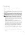 7
7
-
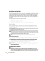 8
8
-
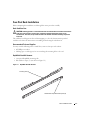 9
9
-
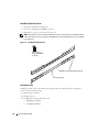 10
10
-
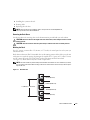 11
11
-
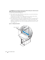 12
12
-
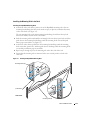 13
13
-
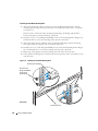 14
14
-
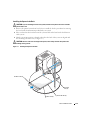 15
15
-
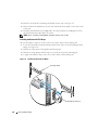 16
16
-
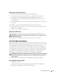 17
17
-
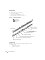 18
18
-
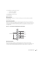 19
19
-
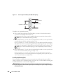 20
20
-
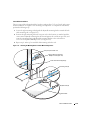 21
21
-
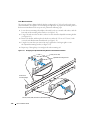 22
22
-
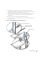 23
23
-
 24
24
-
 25
25
-
 26
26
-
 27
27
-
 28
28
-
 29
29
-
 30
30
-
 31
31
-
 32
32
-
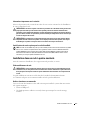 33
33
-
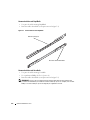 34
34
-
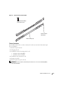 35
35
-
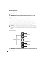 36
36
-
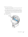 37
37
-
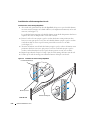 38
38
-
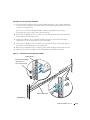 39
39
-
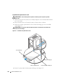 40
40
-
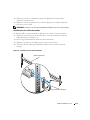 41
41
-
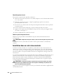 42
42
-
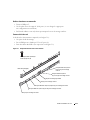 43
43
-
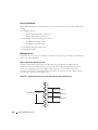 44
44
-
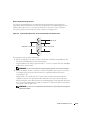 45
45
-
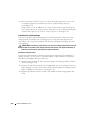 46
46
-
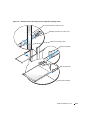 47
47
-
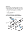 48
48
-
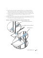 49
49
-
 50
50
-
 51
51
-
 52
52
-
 53
53
-
 54
54
-
 55
55
-
 56
56
-
 57
57
-
 58
58
-
 59
59
-
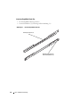 60
60
-
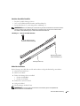 61
61
-
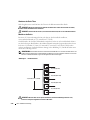 62
62
-
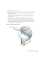 63
63
-
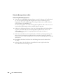 64
64
-
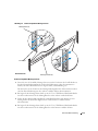 65
65
-
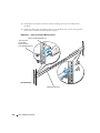 66
66
-
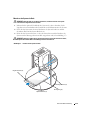 67
67
-
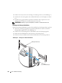 68
68
-
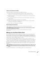 69
69
-
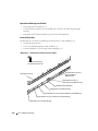 70
70
-
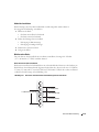 71
71
-
 72
72
-
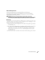 73
73
-
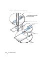 74
74
-
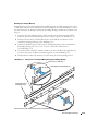 75
75
-
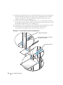 76
76
-
 77
77
-
 78
78
-
 79
79
-
 80
80
-
 81
81
-
 82
82
-
 83
83
-
 84
84
-
 85
85
-
 86
86
-
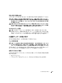 87
87
-
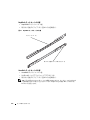 88
88
-
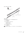 89
89
-
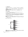 90
90
-
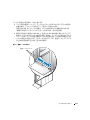 91
91
-
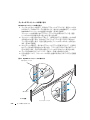 92
92
-
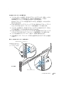 93
93
-
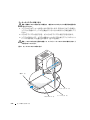 94
94
-
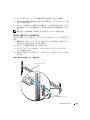 95
95
-
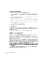 96
96
-
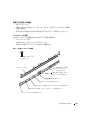 97
97
-
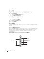 98
98
-
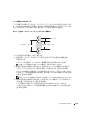 99
99
-
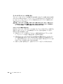 100
100
-
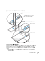 101
101
-
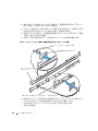 102
102
-
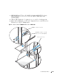 103
103
-
 104
104
-
 105
105
-
 106
106
-
 107
107
-
 108
108
-
 109
109
-
 110
110
-
 111
111
-
 112
112
-
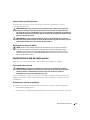 113
113
-
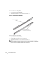 114
114
-
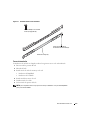 115
115
-
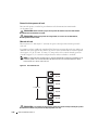 116
116
-
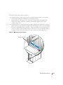 117
117
-
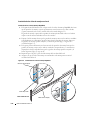 118
118
-
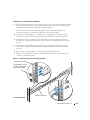 119
119
-
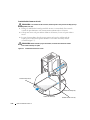 120
120
-
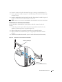 121
121
-
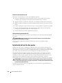 122
122
-
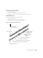 123
123
-
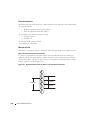 124
124
-
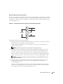 125
125
-
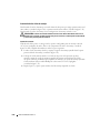 126
126
-
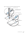 127
127
-
 128
128
-
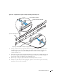 129
129
-
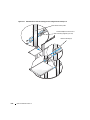 130
130
-
 131
131
-
 132
132
-
 133
133
-
 134
134


Dell PowerEdge 750 Guía del usuario
- Categoría
- Accesorios de rack
- Tipo
- Guía del usuario
en otros idiomas
- français: Dell PowerEdge 750 Mode d'emploi
- Deutsch: Dell PowerEdge 750 Benutzerhandbuch
- 日本語: Dell PowerEdge 750 ユーザーガイド