GE RVM5160DHBB Manual de usuario
- Categoría
- Microondas
- Tipo
- Manual de usuario

Installation
Instructions
Questions? Call 800.GE.CARES (800.432.2737) or Visit our Website at: GEAppliances.com
READ CAREFULLY.
KEEP THESE INSTRUCTIONS.
Read these instructions completely and carefully.
IMPORTANT
–
Save these
instructions for local inspector’s use.
IMPORTANT
–
Observe all
governing codes and ordinances.
Note to Installer
–
Be sure to leave these
instructions with the consumer.
BEFORE YOU BEGIN
Note to Consumer
–
Keep these instructions
for future reference.
6NLOOOHYHO – Installation of this appliance requires basic
mechanical and electrical skills.
Proper installation is the responsibility of the installer.
Product failure due to improper installation is not
covered under the warranty.
2YHUWKH5DQJH
0LFURZDYH2YHQ
AVM4160, JNM3161, JVM3160,
and RVM5160
49-40675-2
(12-13 GE)
Pop
cor
n
Co
nve
nience Cooking
Ex
pr
ess
Co
ok
Pota
to
S
t
a
rt
Pause
Ca
nce
l
Of
f
Bever
ag
e
Rehe
a
t
Se
t
Clock
Turnt
able
S
ur
fa
c
e
Light
Ve
nt
A
d
d
30
Sec.
Po
w
er
Le
v
el
0
8
5
2
7
4
1
9
6
3
C
ook
Ti
m
e
De
f
rost
W
ei
g
ht
/T
ime
Ti
me
r
O
n/O
ff
Pop
cor
n
Co
n
venience Cooking
Ex
pr
ess Co
ok
P
ota
to
S
t
a
rt
Pause
Ca
nce
l
Of
f
Bever
age
Rehe
a
t
Se
t
Clock
Turnt
able
S
ur
fa
c
e
Light
Ve
nt
A
d
d
30
Sec.
Po
w
er
Le
v
el
0
8
5
2
7
4
1
9
6
3
C
ook
Ti
m
e
De
f
ros
t
W
ei
g
ht
/T
ime
Ti
me
r
O
n/O
ff
Throughout this manual, features and appearance may
vary from your model.

2
Outside Back Exhaust .................................. 21-24
Installation Overview ................................ 21
Preparing Rear Wall for
Outside Back Exhaust ................................ 21
Attach Mounting Plate to Wall ..........21, 22
Preparation of Top Cabinet.......................22
Adapting Blower for Outside
Back Exhaust .......................................... 22, 23
Mount the Microwave Oven ..............23, 24
%HIRUH<RX8VH<RXU0LFURZDYH2YHQ ..................... 25
CONTENTS
General information
Important Safety Instructions........................................ 3
Electrical Requirements .................................................. 3
Tools You Will Need ......................................................... 4
Hood Exhaust ................................................................. 5,6
'DPDJH²6KLSPHQW,QVWDOODWLRQ .................................. 7
Parts Included ................................................................... 7
0RXQWLQJ6SDFH ................................................................ 8
6WHSE\VWHSLQVWDOODWLRQJXLGH
3ODFHPHQWRI0RXQWLQJ3ODWH ................................... 9-11
Removing the Mounting Plate ............................. 9
Finding the Wall Studs .......................................... 9
Determining Mounting Plate Location ..............10
Aligning the Mounting Plate .............................. 11
Installation Types ..................................................... 12-23
Recirculating .................................................. 13-16
Attach Mounting Plate to Wall ................13
Preparation of Top Cabinet......................13
Adjust the Blower ...................................... 14
Installing the Charcoal Filter ....................15
Mount the Microwave Oven ..............15, 16
Installing the Charcoal Filter
without Top Access ............................16
Outside Top Exhaust ..................................... 17-20
Attach Mounting Plate to Wall .................17
Preparation of Top Cabinet.......................18
Adjust Blower Motor ..................................18
Assemble and Install Adaptor ..................19
Mount the Microwave Oven ..............19, 20
Connecting Ductwork ................................20
A
B
C
Installation Instructions

A qualified electrician must perform a ground continuity
check on the wall receptacle before beginning the
installation to ensure that the outlet box is properly
grounded. If not properly grounded, or if the wall
receptacle does not meet electrical requirements noted
(under ELECTRICAL REQUIREMENTS), a qualified electrician
should be employed to correct any deficiencies.
WARNING:
5LVNRI(OHFWULF6KRFN
Can cause injury or death:
5HPRYHKRXVHIXVHRU
RSHQFLUFXLWEUHDNHUEHIRUH
EHJLQQLQJLQVWDOODWLRQWRDYRLG
VHYHUHRUIDWDOVKRFNLQMXU\
WARNING:5LVNRI(OHFWULF6KRFN
Can cause injury or death: THIS APPLIANCE MUST BE
PROPERLY GROUNDED WRDYRLGVHYHUHRUIDWDOVKRFN
120 V Models
The power cord of this
appliance is equipped with
DWKUHHSURQJJURXQGLQJ
SOXJZKLFKPDWHVZLWK
DVWDQGDUGWKUHHSURQJ
JURXQGLQJZDOOUHFHSWDFOH
to minimize the possibility
RIHOHFWULFVKRFNKD]DUG
from this appliance.
IMPORTANT SAFETY INSTRUCTIONS
3
ELECTRICAL REQUIREMENTS
Installation Instructions
Ensure proper
ground exists
before use.
CAUTION: For personal safety, the
PRXQWLQJVXUIDFHPXVWEHFDSDEOHRIVXSSRUWLQJWKH
FDELQHWORDGLQDGGLWLRQWRWKHDGGHGZHLJKWRIWKLV
²SRXQGSURGXFWSOXVDGGLWLRQDOPLFURZDYHRYHQ
ORDGVRIXSWRSRXQGVRUDWRWDOZHLJKWRI²
pounds.
CAUTION: For personal safety, this product
FDQQRWEHLQVWDOOHGLQFDELQHWDUUDQJHPHQWVVXFKDVDQ
island or a peninsula. It must be mounted to BOTH a top
FDELQHW$1'DEDFNZDOO
CAUTION:7RDYRLGWKHULVNRISHUVRQDO
LQMXU\EDFNLQMXU\RURWKHULQMXULHVGXHWRH[FHVVLYH
ZHLJKWRIWKHPLFURZDYHRUSURSHUW\GDPDJH\RXZLOO
QHHGWZRSHRSOHWRLQVWDOOWKLVPLFURZDYH
:KHUHDVWDQGDUGWZRSURQJZDOOUHFHSWDFOHLV
encountered, it must be replaced with a properly
JURXQGHGWKUHHSURQJZDOOUHFHSWDFOHLQVWDOOHGE\D
qualified electrician.
WARNING:5LVNRI(OHFWULF6KRFN
Can cause injury or death: DO NOT, under any
FLUFXPVWDQFHVFXWGHIRUPRUUHPRYHDQ\RIWKHSURQJV
from the power cord. Do not use with an extension cord.
Failure to comply may cause fire.
120 V Models
This product requires a three-prong grounded outlet.
Product rating is 120 volts AC, 60 Hertz, 15 amps, and 1.70
kilowatts. This product must be connected to a supply
circuit of the proper voltage and frequency. Wire size must
conform to the requirements of the National Electrical
Code or the prevailing local code for this kilowatt rating.
The power supply cord and plug should be brought to a
separate 15 to 20 ampere branch circuit single grounded
outlet. The outlet box should be located in the cabinet
above the microwave oven and away from any potential
microwave ducting. The outlet box and supply circuit
should be installed by a qualified electrician and conform
to the National Electrical Code or the prevailing local code.

4
Installation Instructions
TOOLS YOU WILL NEED
#1 and #2 Phillips
screwdriver
Pencil
Ruler or tape measure and
straight edge
Carpenter square
(optional)
Tin snips (for cutting
damper, if required)
Electric drill with
3
ø16s,
7
ø16s,
1
ø2s and
5
ø8s drill bits
Hammer (optional)
Stud finder
Filler blocks or scrap
wood pieces, if needed
for top cabinet spacing
(used on recessed bottom
cabinet installations only)
Gloves
Saw (saber, hole or keyhole)
Level
Duct and masking
tape
Scissors (to cut
template, if necessary)
Safety goggles

5
Installation Instructions
HOOD EXHAUST
NOTE: 5HDGWKHVHQH[WWZRSDJHVRQO\LI\RXSODQWRYHQW\RXUH[KDXVWWRWKHRXWVLGH,I\RXSODQWRUHFLUFXODWHWKHDLU
EDFNLQWRWKHURRPSURFHHGWRSDJH
6.%HORZDUHH[DPSOHVRI2XWVLGH7RS([KDXVWDQG2XWVLGH%DFN([KDXVWGXFWV\VWHP
OD\RXWV1RWHWKHSRVLWLRQRIWKHPLFURZDYHRYHQUHODWLYHWRWKHGXFWV\VWHP
2876,'(723(;+$867(;$03/(21/<
EQUIVALENT NUMBER EQUIVALENT
DUCT PIECES LENGTH x USED = LENGTH
Roof Cap 24 Ft. x (1) = 24 Ft.
12 Ft. Straight Duct 12 Ft. x (1) = 12 Ft.
(6s Round)
Rectangular-to-Round 5 Ft. x (1) = 5 Ft.
Transition Adaptor*
Equivalent lengths of duct pieces are based on actual tests and
reflect requirements for good venting performance with any vent hood.
7RWDO/HQJWK )W
* IMPORTANT: If a rectangular-to-round transition adaptor is used, the bottom corners of the damper will
have to be cut to fit, using the tin snips, in order to allow free movement of the damper.
The following chart describes an example of one possible
ductwork installation.
The following chart describes an example of one possible
ductwork installation.
NOTE: For back exhaust, care should be taken to align exhaust with space between studs, or wall should be prepared
at the time it is constructed by leaving enough space between the wall studs to accommodate exhaust.
2876,'(%$&.(;+$867(;$03/(21/<
EQUIVALENT NUMBER EQUIVALENT
DUCT PIECES LENGTH* x USED = LENGTH
Wall Cap 40 Ft. x (1) = 40 Ft.
3 Ft. Straight Duct 3 Ft. x (1) = 3 Ft.
(3
1
ø4s x 10s Rectangular)
90° Elbow 10 Ft. x (2) = 20 Ft.
Equivalent lengths of duct pieces are based on actual tests and
reflect requirements for good venting performance with any vent hood.
7RWDO/HQJWK )W

EQUIVALENT NUMBER EQUIVALENT
DUCT PIECES LENGTH x USED = LENGTH
Rectangular-to-Round 5 Ft. x ( ) = Ft.
Transition Adaptor*
Wall Cap 40 Ft. x ( ) = Ft.
90° Elbow 10 Ft. x ( ) = Ft.
45° Elbow 5 Ft. x ( ) = Ft.
90° Elbow 25 Ft. x ( ) = Ft.
45° Elbow 5 Ft. x ( ) = Ft.
Roof Cap 24 Ft. x ( ) = Ft.
Straight Duct 6s Round or 1 Ft. x ( ) = Ft.
3
1
ø4s x 10s Rectangular
7RWDO'XFWZRUN )W
Equivalent lengths of duct pieces are based on actual tests and
reflect requirements for good venting performance with any vent
hood.
6
* IMPORTANT: If a rectangular-to-round transition
adaptor is used, the bottom corners of the damper
will have to be cut to fit, using the tin snips, in order
to allow free movement of the damper
.
NOTE: If you need to install ducts, note that the total duct
length of 3
1
ø4s x 10s rectangular or 6s diameter round duct
VKRXOGQRWH[FHHGHTXLYDOHQWIHHW
Outside ventilation requires a HOOD EXHAUST DUCT.
Read the following carefully:
NOTE: It is important that venting be installed using
the most direct route and with as few elbows as possible.
This ensures clear venting of exhaust and helps prevent
blockages. $OVRPDNHVXUHGDPSHUVVZLQJIUHHO\DQG
QRWKLQJLVEORFNLQJWKHGXFWV
Exhaust connection:
The hood exhaust has been designed to mate with
a standard 3
1
ø4s x 10s rectangular duct.
If a round duct is required, a rectangular-to-round
transition adaptor must be used. Do not use less than
a 6s diameter duct.
0D[LPXPGXFWOHQJWK
For satisfactory air movement, the total duct length of
3
1
ø4s x 10s rectangular or 6s diameter round duct should
QRWH[FHHGHTXLYDOHQWIHHW
Elbows, transitions, wall and roof caps, etc.,
present additional resistance to airflow and are equivalent
to a section of straight duct which is longer than their actual
physical size. When calculating the total duct length, add the
equivalent lengths of all transitions and adaptors plus the
length of all straight duct sections. The chart below shows
you how to calculate total equivalent ductwork length using
the approximate feet of equivalent length of some typical
duct pieces.
Installation Instructions

PART QUANTITY
Top Cabinet
Template
1
Rear Wall
Template
1
Installation
Instructions
and
Owners
Manual
1
1
Grease
Filters
2
Exhaust
Adaptor
1
Tray 1
Turntable
Ring
1
Charcoal
Filter
(on some
models)
1*
PART QUANTITY
Wood Screws
(3/16” x 2”)
2
Toggle Bolts (and
wing nuts) (1/4” x 3”)
4
Self-aligning Machine
Screw
(1/4”-28 x
3-1/4”)
3
Nylon Grommet (for
metal cabinets)
2
Power Cord Strap
(plastic)
1
7
Installation Instructions
,IWKHXQLWLVGDPDJHGLQVKLSPHQW return
the unit to the store in which it was bought for
repair or replacement.
,IWKHXQLWLVGDPDJHGE\WKHFXVWRPHU repair or
replacement is the responsibility of the customer.
,IWKHXQLWLVGDPDJHGE\WKHLQVWDOOHU (if other than
the customer), repair or replacement must
be made by arrangement between customer
and installer.
'$0$*(²6+,30(17
INSTALLATION
PARTS INCLUDED
INSTALLATION
INSTRUCTIONS
OWNER
S
MANUA
L
ADDITIONAL PARTS
PARTS INCLUDED
You will find the installation hardware contained
in a packet with the unit. Check to make sure you
have all these parts.
NOTE:
Some extra parts are included.
HARDWARE PACKET
≤
≤
≤
* NOTE:
)RU-90DQG$90, filter is in accessory pack.
It is not installed in the product.
)RU-10filter is already installed in the product.
)RU590 filter not included.

8
Installation Instructions
MOUNTING SPACE
NOTES:
The space between the cabinets must be 30s wide
and free of obstructions.
If the space between the cabinets is greater than
30s, a Filler Panel Kit may be used to fill in the gap
between the microwave oven and the cabinets.
Your Owner’s Manual contains the kit number for
your model.
This microwave oven is for installation over ranges
up to 36s wide.
If you are going to vent your microwave oven to the
outside, see Hood Exhaust Section for exhaust duct
preparation.
When installing the microwave oven beneath
smooth, flat cabinets, be careful to follow the
instructions on the top cabinet template for power
cord clearance.
0D[LPXPFDELQHWGHSWKDERYHDQGEHVLGHWKHXQLW
is 12¾s.
)RUPRGHOVVHWXSLQ5HFLUF([KDXVW'RQRWDOORZ
cabinetry or other objects to block the airflow of the
vent.
7KHSURGXFWVKRXOGQRWEHLQVWDOOHGRYHUDQ\FRRNWRS
or range with a combined BTU greater than 60,000
BTU.
Backsplash
66s or
more from
the floor
to the
top of the
microwave
oven
30s
2s
30s
min.
16-½s
Bottom edge of
cabinet needs to
be 30s or more
from the cooking
surface
12¾s
max.

9
Installation Instructions
Find the studs, using one of the following methods:
A. Stud finder.
OR
B. Use a hammer to tap lightly across the mounting
surface to find a solid sound. This will indicate
a stud location.
After locating the stud(s), find the center by probing
the wall with a small nail to find the edges of the stud.
Then place a mark halfway between the edges.
The center of any adjacent studs should be 16s or 24s
from this mark.
Draw a line down the center of the studs.
IMPORTANT: The microwave must be connected to at
least one wall stud.
1
Open the box and fold back all four carton flaps fully
against the carton sides. Remove the following items
from the protective foam: installation instructions,
filters, exhaust adaptor, damper, and the small
hardware bag. Do not remove the foam protecting
the front of the microwave oven.
Then carefully roll the microwave oven and carton
over onto the top side. The microwave oven should
be resting in the foam.
REMOVING THE MICROWAVE
29(1)5207+(&$5721
REMOVING THE MOUNTING PLATE
FINDING THE WALL STUDS
B
A
2
PLACEMENT OF THE MOUNTING PLATE
1
Wall
Studs
Center
3
Carton
Pull the carton up and off the microwave oven.
Open the microwave oven door and remove the
plastic sheet and tape from inside the microwave
oven door. Remove the tape covering the turntable
hub.
Foam
2
3
6
Set the microwave oven upright. Remove and
properly discard plastic bags and foam.
1
The mounting plate is attached to the back of the
microwave oven. Remove the two screws holding it
to the microwave oven. The plate will be used as the
rear wall template and for mounting the microwave
oven to the wall.
4
5

10
DETERMINING MOUNTING PLATE LOCATION UNDER YOUR CABINET
C
Your cabinets may have decorative trim that interferes
with the microwave oven installation. You may need to
remove the decorative trim to install the microwave oven
properly and to make it level.
THE MICROWAVE OVEN MUST BE LEVEL.
Use a level to make sure the cabinet bottom is level.
If the cabinets have a front overhang, install the
mounting plate down the same distance as the front
overhang depth. This will keep the microwave oven level.
Measure the inside depth of the front overhang.
Draw a horizontal line on the back wall an equal
distance below the cabinet bottom as the inside depth
of the front overhang.
For this type of installation with front overhang,
align the mounting tabs with this horizontal line, not
touching the cabinet bottom as described in Step D.
Plate Position – flat bottom cabinet
3ODWH3RVLWLRQ²FDELQHWZLWKIURQWRYHUKDQJ
Mounting Plate Tabs
Touching the Cabinet
Bottom
Mounting Plate
with Tabs Below
Cabinet Bottom
the Same Distance
as the Front
Overhang Depth
At least 30s, up to 36s
Plate Position – recessed cabinet bottom
Mounting Plate
Tabs Touching the
Back Frame of the
Cabinet
30s to Cooktop
30s to Cooktop
1
2
3
Installation Instructions

11
Installation Instructions
ALIGNING THE MOUNTING PLATE
Draw a vertical line on the wall at the center of the 30s
wide space.
Use the mounting plate as the template for the rear wall.
Place the mounting plate on the wall, making sure that
the tabs are WRXFKLQJWKHERWWRPRIWKHFDELQHWRU
WKHOHYHOOLQHGUDZQLQ6WHS&IRUFDELQHWVZLWKIURQW
RYHUKDQJ/LQHXSWKHQRWFKDQGFHQWHUOLQHRQ
WKHPRXQWLQJSODWHWRWKHFHQWHUOLQHRQWKHZDOO
While holding the mounting plate with one hand, draw
circles on the wall at holes A, B, C, and D (see illustration
above/actual plate marked with arrows) . Four holes
PXVWEHXVHGIRUPRXQWLQJ
NOTE: Holes C and D are inside area E. If neither C nor D
is in a stud, find a stud somewhere in area E and draw a
fifth circle to line up with the stud. It is important to use
at least one wood screw mounted firmly in a stud
to support the weight of the microwave oven.
6HWWKHPRXQWLQJSODWHDVLGH
WARNING:5LVNRIHOHFWULFVKRFN&DQFDXVH
LQMXU\RUGHDWK7DNHFDUHWRQRWGULOOLQWRHOHFWULFDOZLULQJ
inside walls or cabinets.
Drill holes on the circles. If there is a stud, drill a
3
ø16s hole
for wood screws. For holes that don’t line up with a stud,
drill a
5
ø8s hole for toggle bolts.
NOTE: DO NOT MOUNT THE PLATE AT THIS TIME.
2
3
4
Draw a
Vertical Line
on Wall from
Center of Top
Cabinet
Area E
Hole A
Hole B
Hole D
Notch
Hole C
D
CAUTION:
:HDUJORYHVWRDYRLGFXWWLQJ
ILQJHUVRQVKDUSHGJHV
1
30”

12
This microwave oven is designed for adaptation to the
following 3 types of ventilation:
$5HFLUFXODWLQJ1RQ9HQWHG'XFWOHVV
%2XWVLGH7RS([KDXVW9HUWLFDO'XFW
&2XWVLGH%DFN([KDXVW+RUL]RQWDO'XFW
127(6HOHFWWKHW\SHRIYHQWLODWLRQUHTXLUHGIRU\RXU
installation and proceed to that section.
P
op
c
orn
C
on
v
e
ni
e
nc
e
C
oo
k
in
g
E
x
pr
e
ss
C
oo
k
P
o
t
at
o
S
t
ar
t
Pa
u
se
C
an
c
e
l
Off
B
ev
e
r
ag
e
R
e
he
a
t
Set
Cloc
k
Tur
ntab
l
e
S
ur
f
ac
e
Li
gh
t
V
en
t
A
d
d
30 Se
c.
Po
w
e
r
L
e
v
e
l
0
8
5
2
7
4
1
9
6
3
Cook
T
i
m
e
D
e
f
r
ost
W
ei
gh
t/
Ti
m
e
T
i
m
e
r
O
n
/
O
f
f
B
OUTSIDE TOP EXHAUST
9(57,&$/'8&7
6HHSDJH
Adaptor in Place for
Outside Top Exhaust
2
OUTSIDE BACK EXHAUST
+25,=217$/'8&7
P
opco
r
n
C
on
v
e
ni
e
nc
e
C
oo
k
in
g
E
x
pr
e
ss C
oo
k
P
o
tat
o
S
t
ar
t
Pau
se
C
an
ce
l
Off
B
ev
e
r
ag
e
R
eh
e
at
Set
Cloc
k
Tur
n
table
Su
rf
ac
e
Li
gh
t
Ve
nt
Ad
d
30 Se
c.
Po
w
e
r
L
e
ve
l
0
8
5
2
7
4
1
9
6
3
Cook
T
i
m
e
D
e
f
r
os
t
W
ei
gh
t
/Time
Ti
m
e
r
O
n/O
f
f
6HHSDJH
C
RECIRCULATING
1219(17(''8&7/(66
P
op
c
or
n
C
on
v
eni
enc
e
C
oo
k
in
g
Express
C
oo
k
P
ot
at
o
S
t
art
Pa
use
C
an
ce
l
Off
B
eve
rag
e
R
eh
e
at
Set
Cl
oc
k
Tu
r
n
t
abl
e
Su
rf
ac
e
L
i
gh
t
Ve
nt
A
d
d
30 Se
c
.
Po
we
r
Le
ve
l
0
8
5
2
7
4
1
9
6
3
Cook
T
i
m
e
De
fr
os
t
W
eigh
t/
T
im
e
T
i
m
e
r
O
n
/
O
f
f
6HHSDJH
A Charcoal Filter Accessory Kit is required for the non-vented
exhaust. (See your Owner’s Manual for the kit number.)
A
Installation Instructions
INSTALLATION TYPES
&KRRVH$%RU&

Installation Instructions
13
USE TOP CABINET TEMPLATE
FOR PREPARATION OF TOP CABINET
A2
RECIRCULATING 1RQ9HQWHG'XFWOHVV
P
o
p
c
o
r
n
C
o
n
v
e
n
i
e
n
ce
C
o
o
k
i
n
g
Expr
e
s
s
C
o
o
k
P
o
ta
to
St
ar
t
P
a
u
s
e
C
an
ce
l
O
f
f
Be
v
e
r
a
ge
R
eh
e
a
t
S
e
t
C
l
o
ck
T
u
rnt
a
b
l
e
S
ur
f
a
c
e
L
i
g
ht
V
e
nt
A
d
d
3
0
S
e
c
.
Po
we
r
L
e
v
e
l
0
8
5
2
7
4
1
9
6
3
C
o
o
k
Ti
me
D
e
f
ro
s
t
W
e
i
g
ht
/T
i
me
T
i
m
e
r
O
n
/O
f
f
INSTALLATION OVERVIEW
A1. Attach Mounting Plate to Wall
A2. Prepare Top Cabinet
A3. Adjust Blower Motor
A4. Install Charcoal Filter
A5. Mount the microwave oven
A6. Installing/Replacing the Charcoal Filter Without
Access to Top Screws and the Unit Has Already
Been Mounted.
Read the instructions on the TOP CABINET
TEMPLATE.
Tape it underneath the top cabinet.
Drill the holes, following the instructions on the TOP
CABINET TEMPLATE.
CAUTION::HDUVDIHW\JRJJOHVZKHQ
GULOOLQJKROHVLQWKHFDELQHWERWWRP
You need to drill holes for the top support screws and
a hole large enough for the power cord to fit through.
A
Place the mounting plate against the wall and insert
the toggle wings into the holes in the wall to mount
the plate.
NOTE: Before tightening toggle bolts and wood screw,
make sure the tabs on the mounting plate touch the
bottom of the cabinet or the horizontal level line when
pushed flush against the wall and that the plate is
properly centered under the cabinet.
CAUTION:%HFDUHIXOWRDYRLGSLQFKLQJ
ILQJHUVEHWZHHQWKHEDFNRIWKHPRXQWLQJSODWHDQG
the wall.
Tighten all bolts. Pull the plate away from the wall
to help tighten the bolts.
3
ATTACH THE MOUNTING PLATE
TO THE WALL
A1
Attach the plate to the wall using toggle bolts. At least
one wood screw must be used to attach the plate to
a wall stud.
Remove the toggle wings from the bolts.
Insert the bolts into the mounting plate through
the holes designated to go into drywall and reattach
the toggle wings to
3
ø4s onto each bolt.
1
4
Wall
Mounting
Plate
Spacing for Toggles More
Than Wall Thickness
Bolt End
Toggle
Bolt
Toggle Wings
7RXVHWRJJOHEROWV:
2

Installation Instructions
14
ADJUST BLOWER MOTOR
A3
Remove the screws holding the blower unit and
the screws securing the blower plate. Remove
the blower plate from the outer case by sliding it
toward the back of the microwave and pulling up.
1
Blower Plate
Blower Motor Screws
Blower
Motor
Screw
2
Carefully pull out the blower unit. The wires will
extend far enough to allow you to adjust the
blower unit.
$'-867%/2:(502725FRQW
A3
Roll the blower so that fan blade openings are
facing the top of the oven. Place the blower back
into the opening.
Slide the blower plate back onto the microwave
by placing the side tabs into the slots and pushing
gently until the back tab is seated into the rear slot.
Replace 3 screws.
Note: Make sure the wires remain routed through the
openings in the motor frame. To avoid damage to
the fan motor wiring, insert motor carefully such that
the fan motor wiring does not contact the microwave
power cord bracket.
3
4
Back of
Mircrowave
Rotate 90°
WARNING: 5LVNRI(OHFWULF6KRFN
Can cause injury or death. Do not pull or stretch the
EORZHUXQLWZLULQJ0DNHVXUHWKHZLUHVDUHQRW
pinched.
Side Tab
Side Slot
Rear Slot
Rear Tab
Back of
Mircrowave
Fan Blades
Wires

Installation Instructions
A5
CAUTION: 7RDYRLGWKHULVNRISHUVRQDO
LQMXU\EDFNLQMXU\RURWKHULQMXULHVGXHWRH[FHVVLYH
ZHLJKWRIWKHPLFURZDYHRUSURSHUW\GDPDJH\RX
ZLOOQHHGWZRSHRSOHWRLQVWDOOWKLVPLFURZDYH
IMPORTANT: Do not grip or use handle during
installation.
WARNING: 5LVNRI(OHFWULF6KRFN&DQ
FDXVHLQMXU\RUGHDWK,ILQVWDOOLQJXQLWZLWKPHWDO
FRXQWHUWRSVFRYHUWKHHGJHRIWKHSRZHUVXSSO\
FRUGKROHZLWKWKHSRZHUVXSSO\FRUGEXVKLQJ
IMPORTANT: If filler blocks are not used, case damage
may occur from overtightening screws.
MOUNT THE MICROWAVE OVEN
NOTE: When mounting the microwave, thread power
cord through hole in bottom of top cabinet. Keep it
tight throughout Steps 1–3. Do not pinch cord or lift
microwave oven by pulling cord.
Lift microwave, tilt it forward, and hook slots at
back bottom edge onto four lower tabs of mounting
plate.
Rotate front of microwave oven up against cabinet
bottom.
1
2
P
o
p
c
o
r
n
Co
n
v
e
n
ie
n
ce
Co
o
k
i
n
g
E
x
p
r
e
ss
Co
o
k
P
o
t
at
o
S
ta
r
t
P
a
u
s
e
Ca
n
ce
l
O
f
f
B
e
ve
r
a
g
e
R
eh
e
a
t
Se
t
C
l
o
c
k
T
u
r
n
t
ab
l
e
Su
r
fa
c
e
L
i
gh
t
V
en
t
Ad
d
3
0
S
e
c
.
P
o
we
r
L
e
v
e
l
0
8
5
2
7
4
1
9
6
3
C
o
o
k
T
i
m
e
Def
ro
s
t
W
e
ig
h
t
/
T
i
me
T
i
m
e
r
O
n
/
O
f
f
Power Cord
INSTALLING THE CHARCOAL FILTER
A4
Filter (dashed to show
details of groves)
Bottom Tab
Grooves in
Microwave for
Filter on Each Side
Remove 2 screws on top of microwave oven, just
above the grille panel, using a Phillips screwdriver.
If two screws are not accessible, see section A5.
Open the door.
Remove the grille.
Insert the top of the filter up and into the grooves on
both sides of the inside of the top opening. Once you
have cleared the bottom tab, push the bottom of the
filter in until it rests in place behind the tab.
2
1
3
4
Popcorn
Convenience Cooking
Express Cook
Potato
Start
Pause
Cancel
Off
Beverage
Reheat
Set
Clock
Turntable
Surface
Light
Vent
Add
30 Sec.
Power
Level
0
8
5
2
7
4
1
9
6
3
Cook
Time
Defrost
Weight/Time
Timer
On/Off
Replace the grille by inserting the top grill flange
into the slots in the case as shown.
Replace the 2 top screws.
Close the door.
5
6
7
Grille
Grille
Grille
15
Ensure bottom
tabs are seated
as shown.

16
Installation Instructions
A5
MOUNT THE MICROWAVE OVEN
FRQW
P
o
pc
or
n
C
o
n
v
e
n
i
en
c
e
C
o
o
k
i
n
g
E
xp
re
s
s
C
o
o
k
P
o
t
at
o
S
t
a
rt
P
a
u
s
e
C
a
n
c
e
l
O
f
f
B
ev
e
r
age
R
ehea
t
Se
t
C
lock
Tu
r
nt
abl
e
Su
r
fa
c
e
Li
gh
t
V
en
t
Ad
d
30
S
ec
.
Po
w
e
r
L
e
v
e
l
0
8
5
2
7
4
1
9
6
3
C
o
o
k
T
i
m
e
D
ef
r
o
s
t
W
e
i
g
h
t/
T
i
m
e
Ti
m
e
r
O
n
/
O
f
f
5
4
Tighten the three screws to the top of the
microwave oven. (While tightening screws, hold
the microwave oven in place against the wall and
the top cabinet.)
Install grease filters. See the Owner’s Manual
packed with the microwave oven.
Insert 3 self-aligning screws (
1
ø4s-28 x 2
1
ø4”) through
outer top cabinet holes. Turn two full turns on each
screw.
3
Cabinet Front
Cabinet Bottom Shelf
Filler Block
Microwave Oven Top
Equivalent
to Depth
of Cabinet
Recess
Self-Aligning Screw
Self-Aligning Screws
This distance
can NOT
exceed 2”
to ensure
proper
installation
,167$//,1*5(3/$&,1*7+(
CHARCOAL FILTER WITHOUT
ACCESS TO TOP SCREWS AND THE
UNIT HAS ALREADY BEEN MOUNTED
A6
DISMOUNT THE MICROWAVE OVEN
CAUTION: 7RDYRLGWKHULVNRISHUVRQDO
LQMXU\EDFNLQMXU\RURWKHULQMXULHVGXHWRH[FHVVLYH
ZHLJKWRIWKHPLFURZDYHRUSURSHUW\GDPDJH\RXZLOO
QHHGWZRSHRSOHWRXQLQVWDOOWKLVPLFURZDYH
IMPORTANT: Do not grip or use handle during removal.
WARNING: 5LVNRI(OHFWULF6KRFN&DQ
FDXVHLQMXU\RUGHDWK,IUHPRYLQJXQLWZLWKPHWDO
FRXQWHUWRSVFRYHUWKHHGJHRIWKHSRZHUVXSSO\FRUG
KROHZLWKWKHSRZHUVXSSO\FRUGQ\ORQJURPPHW
IMPORTANT: If filler blocks are not used, case damage
may occur from overtightening screws.
P
o
pc
o
rn
C
on
v
e
ni
enc
e
C
oo
k
in
g
E
x
pre
s
s C
o
o
k
P
o
tato
S
t
a
rt
P
a
u
s
e
C
a
nc
e
l
O
f
f
B
ev
e
rage
R
eheat
Se
t
C
l
o
ck
Tu
rnt
abl
e
Su
r
fa
c
e
Light
V
en
t
Ad
d
30
S
ec
.
Po
w
e
r
L
e
v
e
l
0
8
5
2
7
4
1
9
6
3
C
o
o
k
T
i
m
e
D
ef
r
o
s
t
W
ei
g
h
t
/
T
i
me
Ti
m
e
r
O
n
/
Of
f
Po
p
c
o
r
n
C
o
n
v
e
ni
enc
e
C
o
o
k
i
ng
Ex
p
re
s
s
C
o
o
k
P
o
t
a
t
o
S
t
ar
t
P
a
u
s
e
C
a
n
c
el
O
ff
B
e
v
e
r
a
g
e
R
e
h
e
a
t
S
e
t
C
lo
c
k
T
ur
n
t
a
bl
e
S
u
r
f
ac
e
L
i
gh
t
V
e
n
t
A
d
d
3
0
S
e
c
.
Pow
e
r
Le
v
e
l
0
8
5
2
7
4
1
9
6
3
C
o
o
k
Ti
m
e
D
e
f
r
o
st
W
e
i
g
h
t
/
T
i
m
e
T
i
m
e
r
O
n
/
O
f
f
Loosen the 3 screws on the top of the microwave
oven (inside the cabinet).
1
Lift microwave, tilt it forward and unhook slots at
back bottom edge from the four lower tabs of the
mounting plate.
2
Replace the filter using instructions from section A4.
Reinstall unit following instructions from A5.
3
4

OUTSIDE TOP EXHAUST
9HUWLFDO'XFW
Insert the toggle wings into the holes in the wall and
place the mounting plate against the wall.
NOTE: Before tightening toggle bolts and wood screw,
make sure the tabs on the mounting plate touch the
bottom of the cabinet when pushed flush against the
wall and that the plate is properly centered under the
cabinet.
CAUTION: %HFDUHIXOWRDYRLGSLQFKLQJ
ILQJHUVEHWZHHQWKHEDFNRIWKHPRXQWLQJSODWHDQG
the wall.
Tighten all bolts. Pull the plate away from the wall
to help tighten the bolts.
3
B
4
ATTACH THE MOUNTING PLATE
TO THE WALL
B1
17
Attach the plate to the wall using toggle bolts. At least
one wood screw must be used to attach the plate to
a wall stud. Recommended locations on the mounting
plate are indicated by A, B, C and D.
Remove the toggle wings from the bolts.
Insert the bolts into the mounting plate through
the holes designated to go into drywall and reattach
the toggle wings to
3
ø4s onto each bolt.
1
Po
p
c
o
r
n
Conve
ni
e
nc
e
Coo
k
i
ng
E
x
p
r
e
s
s
Coo
k
Po
t
a
to
S
t
a
r
t
P
a
us
e
Ca
nc
e
l
O
f
f
B
ev
er
a
g
e
R
eh
ea
t
S
et
Cl
o
ck
Tu
r
n
ta
b
l
e
Su
rf
a
ce
L
i
g
h
t
V
e
n
t
A
d
d
3
0
S
ec
.
Po
w
er
Level
0
8
5
2
7
4
1
9
6
3
C
o
o
k
T
i
me
Def
ro
st
W
e
ig
h
t
/
T
im
e
T
i
mer
O
n
/
O
f
f
INSTALLATION OVERVIEW
B1. Attach Mounting Plate to Wall
B2. Prepare Top Cabinet
B3. Adjust Blower Motor
B4. Install Exhaust Adaptor
B5. Mount Microwave Oven
B6. Connect Ductwork
Wall
Mounting
Plate
Mounting Plate
Spacing for Toggles More
Than Wall Thickness
Bolt End
Toggle
Bolt
Toggle Wings
7RXVHWRJJOHEROWV:
Installation Instructions
2
A
B
C
D

18
USE TOP CABINET TEMPLATE FOR
PREPARATION OF TOP CABINET
You need to drill holes for the top support screws,
a hole large enough for the power cord to fit through,
and a cutout large enough for the exhaust adaptor.
B2
Read the instructions on the TOP CABINET TEMPLATE.
Tape it underneath the top cabinet.
Drill the holes, following the instructions on the TOP
CABINET TEMPLATE.
CAUTION::HDUVDIHW\JRJJOHVZKHQ
GULOOLQJKROHVLQWKHFDELQHWERWWRP
Installation Instructions
ADJUST BLOWER MOTOR
$'-867%/2:(502725FRQW
B3
B3
Remove the screws holding the blower unit and
the screws securing the blower plate. Remove
the blower plate from the outer case by sliding it
toward the back of the microwave and pulling up.
1
Blower Plate
Blower Motor Screws
Blower
Motor
Screw
2
Carefully pull out the blower unit. The wires will
extend far enough to allow you to adjust the
blower unit.
Roll the blower so that fan blade openings are
facing the top of the oven. Place the blower back
into the opening.
Slide the blower plate back onto the microwave
by placing the side tabs into the slots and pushing
gently until the back tab is seated into the rear slot.
Replace 3 screws.
Note: Make sure the wires remain routed through the
openings in the motor frame. To avoid damage to
the fan motor wiring, insert motor carefully such that
the fan motor wiring does not contact the microwave
power cord bracket.
3
4
Back of
Mircrowave
Rotate 90°
Back of
Mircrowave
Fan Blades
Wires
WARNING: 5LVNRI(OHFWULF6KRFN
Can cause injury or death. Do not pull or stretch the
EORZHUXQLWZLULQJ0DNHVXUHWKHZLUHVDUHQRW
pinched.
Side Tab
Side Slot
Rear Slot
Rear Tab

19
Installation Instructions
MOUNT THE MICROWAVE OVEN
B5
CAUTION: 7RDYRLGWKHULVNRISHUVRQDO
LQMXU\EDFNLQMXU\RURWKHULQMXULHVGXHWRH[FHVVLYH
ZHLJKWRIWKHPLFURZDYHRUSURSHUW\GDPDJH\RX
ZLOOQHHGWZRSHRSOHWRLQVWDOOWKLVPLFURZDYH
IMPORTANT: Do not grip or use handle during
installation.
W A R N I N G : 5LVNRI(OHFWULF6KRFN&DQ
FDXVHLQMXU\RUGHDWK,ILQVWDOOLQJXQLWZLWKPHWDO
FRXQWHUWRSVFRYHUWKHHGJHRIWKHSRZHUVXSSO\
FRUGKROHZLWKWKHSRZHUVXSSO\FRUGEXVKLQJ
IMPORTANT: If filler blocks are not used, case damage
may occur from overtightening screws.
NOTE: When mounting the microwave, thread power
cord through hole in bottom of top cabinet. Keep it
tight throughout Steps 1–3. Do not pinch cord or lift
microwave oven by pulling cord.
Lift microwave, tilt it forward, and hook slots at
back bottom edge onto four lower tabs of mounting
plate.
Rotate front of microwave oven up against cabinet
bottom.
1
2
P
o
p
cor
n
Conv
e
nie
nce
Coo
k
ing
E
xp
re
s
s
C
oo
k
P
o
t
a
t
o
Star
t
Pa
u
s
e
Ca
n
ce
l
Of
f
B
e
v
e
r
a
g
e
R
e
h
e
a
t
Se
t
C
l
o
c
k
T
u
rn
t
a
b
l
e
S
u
rf
a
ce
L
i
g
h
t
V
e
n
t
A
d
d
30
S
e
c
.
P
o
w
e
r
L
e
ve
l
0
8
5
2
7
4
1
9
6
3
C
o
ok
T
i
m
e
D
e
f
r
o
s
t
W
e
i
g
h
t
/
T
i
m
e
T
i
me
r
O
n
/
O
f
f
Power Cord
ASSEMBLE AND INSTALL ADAPTOR
B4
Place the microwave oven in its upright position, with
the top of the unit facing up and the front of the unit
facing toward you.
Remove the screw on the back side of the blower
plate and raise the blower plate off of the microwave.
Slide the damper from left to right into the tabs on the
blower plate. The yellow tape on the damper should
be facing away from you.
Remove the yellow tape from the damper. 0DNHVXUH
WKDWWKHGDPSHUSLYRWVHDVLO\EHIRUHPRXQWLQJ
PLFURZDYHRYHQ
You will need to make adjustments to assure proper
alignment with your house exhaust duct after the
microwave oven is installed.
Position the blower plate with damper back on the
microwave and secure it with the screws that were
removed.
1
2
3
4
5
Damper
Blower
Plate

CONNECTING DUCTWORK
20
3
Po
p
cor
n
Co
n
v
e
n
i
e
n
c
e
Co
o
ki
n
g
Ex
p
r
e
ss
Co
o
k
P
o
t
a
t
o
S
t
ar
t
P
a
u
s
e
Ca
nc
e
l
O
ff
B
e
v
e
r
a
g
e
R
e
h
e
a
t
S
et
Cl
o
ck
Tu
r
n
t
a
b
l
e
S
u
r
f
a
c
e
Li
g
h
t
Ve
n
t
Ad
d
3
0
Se
c.
P
o
w
e
r
L
e
v
e
l
0
8
5
2
7
4
1
9
6
3
C
oo
k
T
im
e
D
e
f
ro
s
t
W
e
ig
h
t/T
im
e
T
imer
O
n
/
O
ff
Cabinet Front
Cabinet Bottom Shelf
Filler Block
Microwave Oven Top
Equivalent
to Depth
of Cabinet
Recess
Insert a self-aligning screw through top-center
cabinet hole. Temporarily secure the microwave
oven by turning the screw at least two full
turns after the threads have engaged. (It will be
completely tightened later.) Insert 2 self-aligning
screws (
1
ø4s-28 x 2
1
ø4
s
) through outer top cabinet
holes. Turn two full turns on each screw.
Tighten the three screws to the top of the microwave
oven. (While tightening screws, hold the microwave
oven in place against the wall and the top cabinet.)
Install grease filters. See the Owner’s Manual packed
with the microwave oven.
5
4
Installation Instructions
1
2
Extend the house duct down to connect to
the exhaust adaptor.
Seal exhaust duct joints using duct tape.
P
op
co
r
n
Co
n
ve
n
i
e
n
c
e
Co
ok
i
n
g
Ex
p
res
s Co
ok
Po
ta
t
o
S
tar
t
P
au
s
e
Can
c
el
O
ff
B
e
v
er
a
g
e
R
ehea
t
Set
Cl
oc
k
Tu
r
n
t
a
b
l
e
Su
rf
a
ce
L
i
g
h
t
Ven
t
Ad
d
3
0
S
e
c
.
P
o
w
e
r
Le
ve
l
0
8
5
2
7
4
1
9
6
3
Cook
T
i
m
e
D
ef
ro
st
W
e
i
gh
t
/
Ti
me
Ti
m
e
r
O
n
/O
f
f
House Duct
Self-Aligning Screw
MOUNT THE MICROWAVE OVEN
FRQW
B5
B6
This distance
can NOT
exceed 2”
to ensure
proper
installation

OUTSIDE BACK EXHAUST
+RUL]RQWDO'XFW
PREPARING THE REAR WALL
FOR OUTSIDE BACK EXHAUST
C1
Po
p
c
o
r
n
Co
n
v
e
ni
e
n
ce
Co
o
ki
ng
E
x
p
r
e
s
s
Co
o
k
P
o
t
a
to
S
t
a
rt
Pa
us
e
C
a
nce
l
O
ff
B
evera
g
e
R
e
h
eat
S
et
C
l
o
c
k
T
u
rn
t
a
b
l
e
Surf
a
c
e
Li
g
h
t
V
en
t
A
d
d
3
0
Sec
.
Po
wer
L
evel
0
8
5
2
7
4
1
9
6
3
C
o
o
k
T
i
me
D
ef
r
o
s
t
W
e
igh
t
/
T
im
e
T
i
me
r
O
n
/
O
f
f
INSTALLATION OVERVIEW
C1. Prepare Rear Wall
C2. Attach Mounting Plate to Wall
C3. Prepare Top Cabinet
C4. Adjust Blower
C5. Mount the Microwave Oven
Installation Instructions
C
21
ATTACH THE MOUNTING PLATE
TO THE WALL
C2
Attach the plate to the wall using toggle bolts. At least
one wood screw must be used to attach the plate to
a wall stud.
Remove the toggle wings from the bolts.
Insert the bolts into the mounting plate through
the holes designated to go into drywall and reattach
the toggle wings to
3
ø4s onto each bolt.
1
2
You need to cut an opening in the rear wall for outside
exhaust.
Read the instructions on the REAR WALL TEMPLATE.
Tape it to the rear wall, lining up with the holes
previously drilled for holes A and B in the mounting
plate.
Cut the opening, following the instructions of the
REAR WALL TEMPLATE.

2
1
Remove the blower motor screws that holds the blower
plate to the microwave oven. Slide the plate toward the
back of the microwave and lift up to remove.
ADAPTING BLOWER FOR
OUTSIDE BACK EXHAUST
C4
Remove screw on the back of the unit.
22
USE TOP CABINET TEMPLATE
FOR PREPARATION OF TOP
CABINET
C3
Read the instructions on the TOP CABINET
TEMPLATE.
Tape it underneath the top cabinet.
Drill the holes, following the instructions on the
TOP CABINET TEMPLATE.
CAUTION::HDUVDIHW\JRJJOHVZKHQ
GULOOLQJKROHVLQWKHFDELQHWERWWRP
Wall
Mounting
Plate
Spacing for Toggles More
Than Wall Thickness
Toggle
Bolt
Toggle Wings
7RXVHWRJJOHEROWV
Bolt
End
Installation Instructions
You need to drill holes for the top support screws and
a hole large enough for the power cord to fit through.
Place the mounting plate against the wall and insert
the toggle wings into the holes in the wall to mount
the plate.
NOTE: Before tightening toggle bolts and wood screw,
make sure the tabs on the mounting plate touch
the bottom of the cabinet when pushed flush against
the wall and that the plate is properly centered under
the cabinet.
CAUTION:%HFDUHIXOWRDYRLGSLQFKLQJ
ILQJHUVEHWZHHQWKHEDFNRIWKHPRXQWLQJSODWHDQG
the wall.
Tighten all bolts. Pull the plate away from the wall
to help tighten the bolts.
3
4
Blower Plate
Blower Motor Screws
The fan needs to be turned 180 degrees to the right
to be in the correct orientation, keeping the blower
part of the fan where the air comes out at the top
of the fan. The wire needs to be reinsterted into the
cage housing once it has been oriented correctly.
4
Back of Microwave
Fan Blades
Wires
3
ATTACH THE MOUNTING PLATE
TO THE WALL cont
C2
Screw
Carefully remove fan from cavity. Remove the wire
from the notch at the bottom of the fan after it is
removed from the cavity.
5
Remove the knockout plates in the back of the unit
with snips.
Back of mircrowave
Knockout Plates:
Snip all 4 webs on
each knockout panel
and remove the metal
knockouts for rear airflow.
Please take care to
remove any sharp edges
created from removing
the knockout plates.

Replace the vent cover on the unit and secure it
to the unit by replacing the two screws that were
removed, with one in the middle hole and one on
either side.
9
6
Installation Instructions
MOUNT THE MICROWAVE OVEN
C5
CAUTION: 7RDYRLGWKHULVNRISHUVRQDO
LQMXU\EDFNLQMXU\RURWKHULQMXULHVGXHWRH[FHVVLYH
ZHLJKWRIWKHPLFURZDYHRUSURSHUW\GDPDJH\RX
ZLOOQHHGWZRSHRSOHWRLQVWDOOWKLVPLFURZDYH
IMPORTANT: Do not grip or use handle during
installation.
WARNING: 5LVNRI(OHFWULF6KRFN&DQ
FDXVHLQMXU\RUGHDWK,ILQVWDOOLQJXQLWZLWKPHWDO
FRXQWHUWRSVFRYHUWKHHGJHRIWKHSRZHUVXSSO\
FRUGKROHZLWKWKHSRZHUVXSSO\FRUGEXVKLQJ
IMPORTANT: If filler blocks are not used, case damage
may occur from overtightening screws.
NOTE: When mounting the microwave, thread power
cord through hole in bottom of top cabinet. Keep it
tight throughout Steps 1–3. Do not pinch cord or lift
microwave oven by pulling cord.
Lift microwave, tilt it forward, and hook slots at
back bottom edge onto four lower tabs of mounting
plate.
Rotate front of microwave oven up against cabinet
bottom.
1
2
P
op
corn
Co
n
v
e
n
i
e
n
ce
Co
o
k
in
g
E
xp
r
e
s
s
Co
o
k
P
ot
a
t
o
S
ta
r
t
Pa
u
se
Ca
n
ce
l
O
ff
B
ev
er
a
g
e
R
e
h
e
a
t
S
e
t
C
l
o
ck
T
u
rn
t
a
b
l
e
S
u
r
f
a
ce
L
i
g
h
t
V
e
n
t
A
d
d
30
Se
c
.
P
o
w
e
r
L
e
ve
l
0
8
5
2
7
4
1
9
6
3
C
o
ok
T
ime
D
e
f
r
o
s
t
W
e
i
g
h
t
/
T
i
m
e
T
i
me
r
O
n
/
O
f
f
Power Cord
ADAPTING BLOWER FOR
OUTSIDE BACK EXHAUSTcont.
C4
Side Tab
Side Slot
Rear Slot
Rear
Tab
7
Replace screw on the back of the unit.
Screw
8
Slide the vent damper on back of the unit with the
hinge at the top.
Slide
exhaust
adaptor into
guides on
microwave
oven rear.
Exhaust
Adaptor
Damper
(hinge side up)
Locking
Tabs
Back of
Microwave
Oven
23
Gently place the fan back into the cavity with the
exhaust portion of the fan at the top and facing the
back of the unit.
Note: Make sure the wires remain routed through
the openings in the motor frame. To avoid damage
to the fan motor wiring, insert motor carefully such
that the fan motor wiring does not contact the
microwave power cord bracket.

P
o
p
c
o
r
n
Co
n
v
en
i
e
n
c
e
Co
o
k
i
n
g
E
xp
r
e
s
s
Co
ok
P
o
t
a
to
S
tart
Pa
u
s
e
Ca
n
c
e
l
O
f
f
Bev
e
r
a
g
e
R
eh
ea
t
S
et
Cl
o
c
k
Tu
r
n
t
a
b
le
Su
r
f
a
c
e
Li
g
h
t
Vent
Ad
d
3
0
S
e
c.
P
o
w
e
r
L
e
v
e
l
0
8
5
2
7
4
1
9
6
3
Co
o
k
T
im
e
De
f
r
o
st
W
e
ig
h
t
/T
im
e
Tim
er
O
n
/
O
ff
24
Installation Instructions
MOUNT THE MICROWAVE OVEN
FRQW
C5
5
Cabinet Front
4
Tighten the three screws to the top of the
microwave oven. (While tightening screws, hold
the microwave oven in place against the wall and
the top cabinet.)
Insert a self-aligning screw through top-center
cabinet hole. Temporarily secure the microwave
oven by turning the screw at least two full
turns after the threads have engaged. (It will be
completely tightened later.) Insert 2 self-aligning
screws (
1
ø4s-28 x 2
1
ø4
s
) through outer top cabinet
holes. Turn two full turns on each screw.
Install grease filters. See the Owner’s Manual
packed with the microwave oven.
Cabinet Bottom Shelf
Filler Block
Microwave Oven Top
Equivalent
to Depth
of Cabinet
Recess
Self-Aligning Screw
This distance
can NOT
exceed 2”
to ensure
proper
installation
3

KEEP INSTALLATION INSTRUCTIONS
FOR THE LOCAL INSPECTOR’S USE.
120 V Models: Plug power cord into
a dedicated 15- to 20-amp electrical outlet.
7
Read the Owner’s Manual.
6
Replace house fuse or turn breaker back on.
4
Remove all packing material from the
microwave oven.
2
Make sure the microwave oven has been
installed according to instructions.
1
25
BEFORE YOU USE YOUR MICROWAVE OVEN
Ensure proper
ground exists
before use.
Installation Instructions
Install turntable and turntable ring in cavity.
3
5
Where a standard two-prong wall receptacle
is encountered, it is very important to have it
replaced with a properly grounded three-prong
wall receptacle, installed by a qualified
electrician.

Installation Instructions
26
Printed in China

Instrucciones
de Instalación
¿Preguntas? Llame a 800.GE.CARES (800.432.2737) o visite nuestro sitio web en:
GEAppliances.com
LEER DETENIDAMENTE.
CONSERVE ESTAS INSTRUCCIONES.
Lea estas instrucciones en su totalidad y
atentamente.
IMPORTANTE
–
Conserve estas
instrucciones para uso del inspector local.
IMPORTANTE
–
Cumpla con todos los
códigos y ordenanzas gubernamentales.
Nota para el Instalador
–
Asegúrese de
entregar estas instrucciones la Consumidor.
ANTES DE COMENZAR
Nota para el Comprador
–
Conserve estas
instrucciones para referencia futura.
1LYHOGHKDELOLGDG– La instalación de este
electrodoméstico requiere un nivel básico de
habilidades mecánicas y eléctricas.
La correcta instalación del producto es responsabilidad
del instalador.
Si se producen fallas en el producto debido a una
instalación inadecuada, la Garantía no cubrirá las
mismas
Horno microondas para
colocar encima de la estufa
AVM4160, JNM3161, JVM3160
y RVM5160
49-40675-2
(12-13 GE)
Pop
cor
n
Co
n
venience Cooking
Ex
pr
ess Co
ok
P
ota
to
S
t
a
r
t
Pause
Can
ce
l
Of
f
Bever
age
Rehe
a
t
Se
t
Clock
Turnt
able
S
ur
fac
e
Light
Ve
nt
A
d
d
30
Sec.
Po
w
er
Le
v
el
0
8
5
2
7
4
1
9
6
3
C
ook
Ti
m
e
De
f
rost
W
ei
g
ht
/T
ime
Ti
m
e
r
O
n/O
f
f
Pop
cor
n
Co
n
venien
ce
Co
oking
Ex
pr
es
s
Co
ok
Pota
to
S
t
a
rt
Pause
Ca
n
ce
l
Of
f
Bever
ag
e
Rehea
t
Se
t
C
lo
ck
Turnt
able
S
ur
fa
c
e
Light
Ve
nt
A
d
d
30
Sec.
Po
w
er
Le
v
el
0
8
5
2
7
4
1
9
6
3
C
ook
Ti
m
e
De
f
rost
W
ei
g
ht
/T
ime
Ti
m
e
r
O
n/O
ff
Su modelo puede tener otras características y apariencia que
las ilustradas en este manual.

2
Escape de Salida Trasero ............................ 21-24
Visión General de la Instalación ...............21
Preparación de la Pared Trasera
para el Escape de Salida Trasero ............21
Adjunte la Placa de Montaje a la Pared
..21, 22
Preparación del Gabinete Superior .........22
Adaptación del Calentador al
Escape de Salida Trasero ....................22, 23
Monto el Horno Microondas ..............23, 24
Antes de Usar su Horno Microondas ........................ 25
CONTENIDOS
Información General
Instrucciones Importantes de Seguridad .................... 3
Requisitos Eléctricos ....................................................... 3
Herramientas Que Necesitará ....................................... 4
Campana de Escape .....................................................5,6
'DxR²(QYtR,QVWDODFLyQ .............................................. 7
3DUWHV,QFOXtGDV ................................................................ 7
Espacio de Montaje .......................................................... 8
*XtDGHLQVWDODFLyQSDVRDSDVR
Colocación de la Placa de Montaje ..........................9-10
Retiro de la Placa de Montaje ............................. 9
Búsqueda de los Montajes de Pared .................. 9
Determinación de la Placa de Montaje ............ 10
Alineación de la Placa de Montaje .................... 11
Tipos de Instalación ................................................. 12-23
Recirculación ................................................ 13-16
Adjunte la Placa de Montaje a la Pared
.13
Preparación del Gabinete Superior ........13
Ajuste el Calentador .........................................14
Cómo Instalar el Filtro de Carbón...................15
Monte el Horno Microondas .............15, 16
Instalación del Filtro de Carbón Sin
Acceso a los Tornillos Superiores .........16
Escape de Salida Superior ........................... 17-20
Adjunte la Placa de Montaje a la Pared .17
Preparación del Gabinete Superior .........18
Ajuste el Motor del Calentador .................18
Ensamble e Instale el Adaptador ............19
Monte el Horno Microondas .............19, 20
Conexión de la Tubería ............................20
A
B
C
Instrucciones de Instalación

Un electricista calificado deberá realizar un control de
la continuidad de la conexión a tierra en el receptáculo
de la pared antes de comenzar con la instalación, a
fin de asegurar que la caja del tomacorriente esté
correctamente conectada a tierra. Si no se encuentra
conectado a tierra de forma correcta, o si el receptáculo
de pared no cumple con los requisitos establecidos (bajo
REQUISITOS ELÉCTRICOS), se deberá solicitar los servicios
de un electricista calificado para corregir cualquier
deficiencia
ADVERTENCIA:
Riesgo de Descarga
Eléctrica.
Puede ocasionar lesiones o
ODPXHUWH5HWLUHHOIXVLEOH
GHOKRJDURGLV\XQWRU
DELHUWRDQWHVGHFRPHQ]DU
ODLQVWDODFLyQDILQGHHYLWDU
OHVLRQHVVHYHUDVRWRWDOHV
por descarga.
ADVERTENCIA: Riesgo de Descarga
Eléctrica. Puede ocasionar lesiones o la muerte: ESTE
ELECTRODOMÉSTICO SE DEBE CONECTAR A TIERRA DE
)250$&255(&7$DILQGHHYLWDUGHVFDUJDVVHYHUDVR
mortales.
Modelos de 120 V
(OFDEOHGHFRUULHQWHGHHVWH
electrodoméstico contiene
XQHQFKXIHGHSDWDV
(conexión a tierra) que se
conecta a un tomacorriente
de pared estándar de
FDEOHVFRQH[LyQD
WLHUUDSDUDPLQLPL]DUOD
SRVLELOLGDGGHULHVJRVGH
descargas eléctricas por
parte del mismo.
INSTRUCCIONES IMPORTANTES DE SEGURIDAD
3
REQUISITOS ELÉCTRICOS
Instrucciones de Instalación
Asegúrese de
contar con una
conexión a
tierra adecuada
antes de usar.
PRECAUCIÓN:3RUUD]RQHVGH
VHJXULGDGODVXSHUILFLHGHPRQWDMHGHEHUiSRGHU
VRSRUWDUODFDUJDGHOJDELQHWHDGHPiVGHOSHVR
DJUHJDGRGHHVWHSURGXFWRGHHQWUH\OLEUDV
DGHPiVGHFDUJDVDGLFLRQDOHVHQHOKRUQRPLFURRQGDV
GHKDVWDOLEUDVRXQSHVRWRWDOGHHQWUH\
OLEUDV
PRECAUCIÓN:3RUUD]RQHVGH
seguridad, este producto no se puede instalar en
DUUHJORVGHDODFHQDWDOHVFRPRXQDLVODRSHQtQVXOD6H
GHEHPRQWDU7$172DXQJDELQHWHVXSHULRU&202D
una pared trasera.
PRECAUCIÓN:$ILQGHHYLWDUHOULHVJR
de lesión personal (lesión en la espalda u otras lesiones
GHELGRDXQSHVRH[FHVLYRGHOKRUQRPLFURRQGDVR
GDxRVVREUHODSURSLHGDGGHEHUiFRQWDUFRQODD\XGD
GHGRVSHUVRQDVSDUDLQVWDODUHVWHKRUQRPLFURRQGDV
Cuando se encuentre un tomacorriente de pared de dos
HQFKXIHVVHGHEHUiUHHPSOD]DUSRUXQRFRQHFWDGRD
WLHUUDGHIRUPDDGHFXDGDGHWUHVFDEOHV\GHEHUiVHU
instalado por un electricista calificado.
ADVERTENCIA: Riesgo de Descarga
Eléctrica. Puede ocasionar lesiones o la muerte: NUNCA,
EDMRQLQJXQDFLUFXQVWDQFLDFRUWHGHIRUPHRHOLPLQH
QLQJXQDGHODVSXQWDVGHOFDEOHGHFRUULHQWH1RXVHXQ
prolongador. Si no se cumple con esto, se podrán
producir incendios.
Modelos de 120 V
Este producto requiere un tomacorriente con conexión
a tierra de tres enchufes. La graduación del producto es
de 120 volts AC, 60 Hertz, 15 amps, y 1.70 kilowatts. Este
producto se debe conectar a un circuito con un suministro
del voltaje y frecuencia correcta. El tamaño del cable
deberá ser conforme a los requisitos del Código Eléctrico
Nacional o del código local obligatorio con relación a la
cantidad de kilowatts. El cable y enfuche del suministro
de corriente se deberán conectar a un tomacorriente
simple con conexión a tierra de un circuito de entre 15
y 20 amperes. La caja del tomacorriente deberá estar
ubicada en el gabinete sobre el horno y alejada de
cualquier conducto posible del horno microondas. La caja
del tomacorriente y el circuito de suministro deberán ser
instalados por un electricista calificado y cumplir con el
Código Eléctrico Nacional o el código local obligatorio.

4
Instrucciones de Instalación
HERRAMIENTAS NECESARIAS
Destornillador
Phillips nº1 y nº2
Lápiz
Regla o cinta métrica y extremo
recto
Escuadra de
carpintero
(opcional)
Tijeras para hojalata (para
cortes en reguladores, si
se requiere)
Taladro eléctrico con brocas
de 3/15”, 7/16”, 1/2”, y 5/8”
Martillo (opcional)
Detector de
montantes
Bloques de llenado o piezas de
fragmentos de madera, si son
necesarios para para generar
espacio en el gabinete superior
(usados en instalaciones de
gabinetes inferiores ahuecados
únicamente)
Guantes
Sierra (sable, agujero o cerradura)
Nivel
Cinta para conductos y
de mascarar
Tijeras (para cortar
plantillas, si es necesario)
Gafas de seguridad

5
Instrucciones de Instalación
CAMPANA DE ESCAPE
127$/HDODVGRVVLJXLHQWHVSiJLQDVVyORVLSODQHDYHQWLODUVXHVFDSHGHVGHODSDUWHH[WHULRU6LSODQHDKDFHUTXHHO
DLUHYXHOYDDFLUFXODUHQODKDELWDFLyQSDVHDODSiJLQD$FRQWLQXDFLyQILJXUDQHMHPSORVGHGLDJUDPDVGHOVLVWHPDGHO
FRQGXFWRGHO(VFDSHGH6DOLGD6XSHULRU\GHO(VFDSHGH6DOLGD7UDVHUR2EVHUYHODSRVLFLyQGHOKRUQRPLFURRQGDVUHODWLYDDO
VLVWHPDGHWXEHUtDV
ESCAPE DE SALIDA SUPERIOR (SÓLO EJEMPLO)
LONGITUD NÚMERO EQUIVALENT
PIEZAS DEL CONDUCTO EQUIVALENTE x USADO =EQUIVALENTE
Tapa del Techo 24 pies x (1) = 24 pies
Conducto Recto
12 pies x (1) = 12 pies
de 12 pies (Círculo de 6”)
Adaptador de Transición
5 pies x (1) = 5 pies
Rectangular a Circular*
Las longitudes equivalentes a las piezas de conductos están basadas
en evaluaciones reales y requisitos de reflejo para un buen rendimiento
de la ventilación con cualquier campana de ventilación.
Longitud Total = 41 pies
* IMPORTANTE: Si se utiliza un adaptador de transición rectangular a circular, las esquinas inferiores del regulador se
deberán cortar para que coincidan, usando las tijeras para hojalata, a fin de permitir un movimiento libre del regulador.
En el siguiente cuadro se describe un ejemplo de una posible instalación de conductos.
En el siguiente cuadro se describe un ejemplo de una posible instalación de conductos.
NOTA: Para el escape trasero, será necesario alinear con cuidado el escape con el espacio entre los montajes, o la pared
deberá ser preparada en el momento de su construcción, dejando espacio suficiente entre los montajes de pared para
ubicar el escape.
ESCAPE DE SALIDA TRASERO (SÓLO EJEMPLO)
LONGITUD NÚMERO LONGITUD
PIEZAS DEL CONDUCTO EQUIVALENTE * x USADO = EQUIVALENTE
Tapas de Pared 40 pies x (1) = 40 pies
Conducto Recto 3 pies x (1) = 3 pies
de 30 Pies (Rectangular
de 3 ¼” x 10”)
Codo de 90º 10 pies x (2) = 20 pies
Longitudes equivalentes a las piezas de conductos en base a evaluaciones
reales y requisitos de reflejo para un buen rendimiento de la ventilación
con cualquier campana de ventilación.
Longitud Total = 63 pies

LONGITUD NÚMERO LONGITUD
PIEZAS DE TUBERÍA EQUIVALENTE x USADO = EQUIVALENTE
Adaptador de Transición 5 pies x ( ) = Pies
Rectangular a Circular*
Tapas de Pared 40 pies x ( ) = Pies
Codo de 90º 10pies x ( ) = Pies
Codo de 45º 5 pies x ( ) = Pies
Codo de 90º 25 pies x ( ) = Pies
Codo de 45º 5 pies x ( ) = Pies
Tapa del Techo 24 pies x ( ) = Pies
Tubería Recta de 6” Circular 1 pies x ( ) = Pies
o 3 ¼” x 10” Rectangular
7XEHUtD7RWDO 3LHV
Las longitudes equivalentes a las piezas de conductos están
basadas en evaluaciones reales y requisitos de reflejo para un
buen rendimiento de la ventilación con cualquier campana de
ventilación.
6
,03257$17(6LVHXWLOL]DXQDGDSWDGRUGHWUDQVLFLyQ
rectangular a circular, las esquinas inferiores del regulador
VHGHEHUiQFRUWDUSDUDTXHFRLQFLGDQXVDQGRODVWLMHUDVSDUD
KRMDODWDDILQGHSHUPLWLUXQPRYLPLHQWROLEUHGHOUHJXODGRU
NOTA: Si necesita instalar tuberías, deberá observar que la
longitud total de una tubería rectangular de 3 1/4” x 10” o
una circular de 6” de diámetroQRGHEHUiVXSHUDUORV
SLHVGHHTXLYDOHQFLD
La ventilación externa requiere un CONDUCTO DE SALIDA DE
LA CAMPANA. Lea la siguiente información detenidamente.
NOTA: Es importante que la ventilación sea instalada
utilizando la ruta más directa y con la menor cantidad de
codos posible. Esto asegura una ventilación despejada del
escape y ayuda a evitar bloqueos. Además, asegúrese de
TXHORVUHJXODGRUHVVHEDODQFHHQOLEUHPHQWH\TXHQDGD
EORTXHHODVWXEHUtDV
Conexión del escape:
El escape de la campana fue diseñado para coincidir con
una tubería rectangular de 3 ¼” x 10”.
Si se requiere una tubería redonda, se deberá usar un
adaptador de transición de rectangular a circular. No use
XQDWXEHUtDGHPHQRVGHµGHGLiPHWUR
/RQJLWXGPi[LPDGHODWXEHUtD
Para un movimiento satisfactorio del aire, la longitud total
de la tubería rectangular de 3 ¼” x 10” o circular 6” de
diámetro QRGHEHUiVXSHUDUORVSLHVGHHTXLYDOHQFLD
Los codos, transiciones, pared y tapas para
WHFKRHWF
presentan resistencia adicional sobre el flujo
de aire y son equivalentes a una sección de una tubería
recta que es más larga que su tamaño físico real. Al calcular
la longitud total de la tubería, agregue las longitudes
equivalentes a todas las transiciones y adaptadores,
además de la longitud de todas las secciones rectas del
conducto. El siguiente cuadro le muestra cómo calcular
la longitud total equivalente de la tubería, usando los pies
aproximados de la longitud equivalente de algunas piezas
de tubería típicas.
Instrucciones de Instalación

PARTE CANTIDAD
Plantilla del
Gabinete
Superior
1
Plantilla de
la Pared
Trasera
1
Instrucciones
de
Instalación
del Manual
del
Propietario
1
1
Filtros de
Grasa
2
Adaptador
del Escape
1
Bandeja 1
Anillo
del Plato
Giratorio
1
Filtro de
Carbón
(en algunos
modelos)
1*
PARTE CANTIDAD
Tornillos de Madera
(3/16” x 2”)
2
Tornillos con resorte
y tuercas mariposa)
(1/4” x 3”)
4
Tornillo de Máquina
con Auto Alineación
(1/4”-28 x 3-1/4”)
3
Arandela Aislante
de Nylon (para
gabinetes metálicos)
2
Cordón para cable
de corriente (plástico)
1
7
Instrucciones de Instalación
6LODXQLGDGVHGDxDGXUDQWHHOHQYtRdevuelva
la unidad a la tienda donde fue comprada para su
reparación o reemplazo.
Si la unidad es dañada por el cliente, la reparación
o reemplazo es responsabilidad del cliente.
6LODXQLGDGHVGDxDGDSRUHOLQVWDODGRU(si no es
el cliente), la reparación o reemplazo deberá ser
realizado por arreglo entre el cliente y el instalador.
'$f2²(19Ë2
INSTALACIÓN
PARTES INCLUIDAS
INSTALLATION
INSTRUCTIONS
OWNER
S
MANUA
L
PIEZAS ADICIONALES
PARTES INCLUIDAS
Enconrará las piezas de instalación dentro de
un paquete con la unidad. Asegúrese de que se
encuentren todas las piezas.
NOTA:
Se incluyen algunas piezas adicionales.
PAQUETE DE PIEZAS
≤
≤
≤
* NOTA:
3DUD-90\$90el filtro está en el paquete de
accesorios. No se encuentra instalado en el producto.
3DUD-10el filtro ya se encuentra instalado en el
producto.
3DUD590 el filtro no está incluido.

8
Instrucciones de Instalación
ESPACIO DE MONTAJE
NOTAS:
El espacio entre los gabinetes debe ser de 30” de
ancho y estar libre de obstrucciones.
Si el espacio entre los gabinetes es superior a 30”,
se podrá usar un Kit de Panel de Relleno para
completar la brecha entre el horno microondas y
los gabinetes. En su Manual del Propietario figura el
número de kit de su modelo.
Este horno microondas debe ser instalado sobre
estufas de hasta 36” de ancho.
Si hará que la ventilación de su horno microondas
salga hacia el exterior, consulte la Sección Escape
de la Campana para la preparación de la tubería de
escape.
Al instalar el horno microondas debajo de gabinetes
lisos y finos, asegúrese de seguir las instrucciones
que figuran en la plantilla del gabinete superior
para que haya un despeje del cable de corriente..
/DSURIXQGLGDGGHOJDELQHWHSRUHQFLPD\DO
FRVWDGRGHODXQLGDGHVGHôµ
3DUDODFRQILJXUDFLyQGHPRGHORVFRQ(VFDSHFRQ
Recirculación: No permita que el gabinete u otros
objetos bloqueen el flujo de aire de la ventilación.
(OSURGXFWRQRGHEHUtDVHULQVWDODGRVREUHXQDSODFD
de cocción o estufa con un BTU combinado superior a
60,000 BTU.
Tablero posterior
66” o más
desde el
piso hasta
la parte
superior
del horno
microondas
30s
2s
Mín. de
30s
16-½s
El extremo inferior
del gabinete debe
estar a 30” o más
desde la superficie
de cocción.
Máx. de
12¾s

9
Instrucciones de Instalación
Busque los montajes, usando uno de los siguientes
métodos:
A. Buscador de montajes.
O
B. Use un martillo para golpear suavemente sobre
la superficie de montaje para buscar un sonido
sólido. Esto indicará la ubicación del montaje.
Luego de ubicar el montaje(s), busque el centro
sondeando la pared con un clavo pequeño para
buscar los extremos del montaje. Luego haga una
marca a mitad de camino entre los extremos. El
centro de cualquier montaje adyacente deberá estar a
16” o 24” desde esta marca.
Dibuje una línea sobre el centro de los montajes.
IMPORTANTE: El horno microondas se deberá conectar
a por lo menos un montaje de pared.
1
Abra la caja y vuelva a doblar las cuatro lengüetas
de la caja completamente contra los costados de la
caja. Retire los siguientes artículos de la gomaespuma
protectora: instrucciones de instalación, filtros,
adaptador del escape, regulador, y la caja pequeña de
piezas. No retire la gomaespuma que protegé el frente
del horno microondas.
Luego con cuidado haga girar el horno microondas y
la caja sobre la parte superior. El horno microondas
deberá descansar sobre la gomaespuma.
RETIRO DEL HORNO MICROONDAS
'(/$&$-$5(7,52'(/3/$72
DE MONTAJE
BÚSQUEDA DEL MONTAJE DE
PARED
B
A
2
COLOCACIÓN DEL PLATO DE MONTAJE
1
Montaje de
Pared
Centro
3
Caja
Empuje la caja hacia arriba y afuera del horno microondas.
Abra la puerta del horno microondas y retire la hoja
plástica y la cinta del interior de la puerta del horno
microondas. Retire la cinta que cubre el centro del
plato giratorio.
Gomaespuma
2
3
6
Coloque el horno microondas en forma vertical.
Retire y de forma apropiada descarte las bolsas de
plástico y la gomaespuma.
1
La placa de montaje está adherida a la parte trasera
del horno microondas. Retire los dos tornillos que la
sostienen al horno microondas. La placa se usará
como la plantilla de la pared trasera y para montar el
horno microondas a la pared.
4
5

10
DETERMINACIÓN DE LA PLACA DE MONTAJE DEBAJO DE SU GABINETE
C
Es posible que sus gabinetes posean bordes decorativos
que interfieren con la instalación del horno microondas.
Es posible que necesite retirar el borde decorativo para
instalar el horno microondas de forma apropiada y
nivelarlo.
EL HORNO MICROONDAS DEBE ESTAR NIVELADO.
Use un nivel para asegurarse de que la parte inferior del
gabinete esté nivelada.
Si los gabinetes cuentan con un frente saliente, instale la
placa de montaje a la misma distancia que la profunidad
del frente saliente. Esto mantendrá el horno microondas
nivelado.
Mida la profundidad interna del frente saliente.
Dibuje una línea horizontal en la pared trasera que
posea la misma distancia debajo del fondo del
gabinete como de la profunidad interior del frente
saliente.
Para este tipo de instalación con frente saliente, alinee
las lengüetas montantes con la línea horizontal, sin
tocar la parte inferior del gabinete como se describe
en el paso D.
3RVLFLyQGHOD3ODFD²JDELQHWHLQIHULRUSODQR
3RVLFLyQGHOD3ODFD²JDELQHWHFRQIUHQWH
saliente
Las lengüetas
de la Placa de
Montaje Tocan la
Parte Inferior del
Gabinete
Placa de Montaje
con Lengüetas
Debajo de la
Parte Inferior del
Gabinete a la
Misma Distancia
que la Profunidad
del Frente Saliente
Por lo menos 30”, hasta 36”
3RVLFLyQGHOD3ODFD²JDELQHWHLQIHULRUKXHFR
Las Lengüetas de
la Placa de Montaje
Tocan la Estructura
Inferior del Gabinete
30” a la Placa de
Cocción
30” a la Placa de Cocción
1
2
3
Instrucciones de Instalación

11
Instrucciones de Instalación
ALINEE LA PLACA DE MONTAJE
Dibuje una línea vertical en la pared en el centro del
espacio de 30” de ancho.
Use la placa de montaje como plantilla para la pared
trasera. Coloque la placa de montaje en la pared,
asegurándose de que las lengüetas estén tocando la
SDUWHLQIHULRUGHOJDELQHWHRODOtQHDDQLYHOGLEXMDGDHQ
HOSDVR&SDUDJDELQHWHVFRQIUHQWHVDOLHQWH$OLQHHOD
UDQXUD\ODOtQHDFHQWUDOGHODSODFDGHPRQWDMHFRQOD
OtQHDFHQWUDOGHODSDUHG
Mientras sostiene la placa de montaje con una mano,
dibuje círculos en la pared en los agujeros A, B, C y D
(consulte la ilustración más arriba/ la placa real está
marcada con flechas). 6HGHEHUiQXVDUFXDWURDJXMHURV
para el montaje.
NOTA: Los agujeros C y D están dentro del área E. Si
C y D no están en un montaje, busque un montaje en
alguna parte en el área E y dibuje un quinto círculo
que se alinee con el montaje. Es importante usar por
lo menos un tornillo de madera montado de manera
firme en un montaje para sostener el peso del horno
microondas.
Deje la placa de montaje a un costado.
ADVERTENCIA: Riesgo de Descarga
(OpFWULFD3XHGHRFDVLRQDUOHVLRQHVRODPXHUWH'HEHUi
WHQHUFXLGDGRGHQRWDODGUDUVREUHFDEOHDGRVHOpFWULFRV
GHQWURGHSDUHGHVRJDELQHWHV
Haga agujeros sobre los círculos. Si hay un montaje,
haga un agujero de 3/16” para tornillos de madera.
Para aquellos agujeros que no estén alineados con un
montaje, haga un agujero de 5/8” para tornillos con
resorte.
NOTA: NO MONTE LA PLACA EN ESTE MOMENTO.
2
3
4
Dibuje una Línea
Vertical en la
Pared desde el
Centro a la Parte
Superior del
Gabinete
Área E
Agujero A
Hole B
Hole D
Ranura
Agujero C
D
PRECAUCIÓN
8VHJXDQWHVSDUDHYLWDUFRUWHVGH
dedos en extremos puntiagudos.
1
30”

12
Este horno microondas está diseñado para ser adaptado a
los siguientes 3 tipos de ventilación:
A. Recirculación (Sin Conductos no Ventilados)
B. Escape Exterior Superior (Conducto Vertical)
&(VFDSH([WHULRU7UDVHUR&RQGXFWR+RUL]RQWDO
127$6HOHFFLRQHHOWLSRGHYHQWLODFLyQUHTXHULGDSDUDVX
LQVWDODFLyQ\SURFHGDDGLFKDVHFFLyQ
P
op
c
orn
C
on
v
e
ni
e
nc
e
C
oo
k
in
g
E
x
pr
e
ss
C
oo
k
P
o
t
at
o
S
t
ar
t
Pa
u
se
C
an
c
e
l
Off
B
ev
e
r
ag
e
R
e
he
a
t
Set
Cloc
k
Tur
ntab
l
e
S
ur
f
ac
e
Li
gh
t
V
en
t
A
d
d
30 Se
c.
Po
w
e
r
L
e
v
e
l
0
8
5
2
7
4
1
9
6
3
Cook
T
i
m
e
D
e
f
r
ost
W
ei
gh
t/
Ti
m
e
T
i
m
e
r
O
n
/
O
f
f
B
ESCAPE EXTERIOR SUPERIOR
(CONDUCTO VERTICAL)
Lea la Página 17.
El Adaptador Está
en el Lugar Correcto
para el Escape
Exterior Superior
2
ESCAPE EXTERIOR TRASERO
(CONDUCTO HORIZONTAL)
P
opco
r
n
C
on
v
e
ni
e
nc
e
C
oo
k
in
g
E
x
pr
e
ss C
oo
k
P
o
tat
o
S
t
ar
t
Pau
se
C
an
ce
l
Off
B
ev
e
r
ag
e
R
eh
e
at
Set
Cloc
k
Tur
n
table
Su
rf
ac
e
Li
gh
t
Ve
nt
Ad
d
30 Se
c.
Po
w
e
r
L
e
ve
l
0
8
5
2
7
4
1
9
6
3
Cook
T
i
m
e
D
e
f
r
os
t
W
ei
gh
t
/Time
Ti
m
e
r
O
n/O
f
f
Lea la Página 21.
C
RECIRCULACIÓN (SIN
CONDUCTOS NO VENTILADOS)
P
op
c
or
n
C
on
v
eni
enc
e
C
oo
k
in
g
Express
C
oo
k
P
ot
at
o
S
t
art
Pa
use
C
an
ce
l
Off
B
eve
rag
e
R
eh
e
at
Set
Cl
oc
k
Tu
r
n
t
abl
e
Su
rf
ac
e
L
i
gh
t
Ve
nt
A
d
d
30 Se
c
.
Po
we
r
Le
ve
l
0
8
5
2
7
4
1
9
6
3
Cook
T
i
m
e
De
fr
os
t
W
eigh
t/
T
im
e
T
i
m
e
r
O
n
/
O
f
f
Lea la Página 13.
Se requiere un Kit de Accesorios de Filtros de Carbón para el
escape no ventilado. (Consulte el número del kit en su Manual
del Propietario).
A
Instrucciones de Instalación
TIPOS DE INSTALACIÓN
(Elija A, B o C)

Instrucciones de Instalación
13
USE LA PLANTILLA DEL GABINETE
SUPERIOR PARA LA PREPARACIÓN DEL
GABINETE SUPERIOR
A2
RECIRCULACIÓN (Sin Conductos No Ventilados)
P
o
p
c
o
r
n
C
o
n
v
e
n
i
e
n
c
e
C
o
o
k
i
n
g
Expr
e
s
s
C
o
o
k
P
o
ta
to
St
ar
t
P
a
u
s
e
C
an
c
e
l
O
f
f
Be
v
e
r
a
g
e
R
eh
e
at
S
e
t
C
l
o
ck
T
u
rnt
a
bl
e
S
u
r
f
a
c
e
L
i
g
ht
V
e
nt
A
dd
3
0
S
e
c
.
Powe
r
L
e
v
e
l
0
8
5
2
7
4
1
9
6
3
C
o
o
k
Ti
me
D
e
f
ro
s
t
W
e
i
g
h
t
/
T
i
me
T
i
m
e
r
O
n
/
O
f
f
VISIÓN GENERAL DE LA INSTALACIÓN
A1. ADHERA LA PLACA DE MONTAJE A LA PARED
A2.
USE LA PLANTILLA DEL GABINETE SUPERIOR PARA LA
PREPARACIÓN DEL GABINETE SUPERIOR
A3.
AJUSTE EL MOTOR DEL CALENTADOR
A4.
CÓMO INSTALAR EL FILTRO DE
CARBÓN
A5. MONTE EL HORNO MICROONDAS
A6.
INSTALACIÓN/ REEMPLAZO DEL FILTRO DE CARBÓN
SIN ACCESO A LOS TORNILLOS SUPERIORES Y LA
UNIDAD YA FUE MONTADA
Lea las instrucciones sobre la PLANTILLA DEL
GABINETE SUPERIOR.
Pegue la misma debajo del gabinete superior.
Haga los agujeros siguiendo las instrucciones en la
PLANTILLA DEL GABINETE SUPERIOR.
PRECAUCIÓN: Use gafas de seguridad
DOUHDOL]DUDJXMHURVHQODSDUWHLQIHULRUGHOJDELQHWH
Es necesario hacer agujeros para los tornillos del
soporte superior y un agujero lo suficientemente grande
para que el cable de corriente lo pueda atravesar.
A
Coloque la placa de montaje contra la pared e
inserte las tuercas mariposa en los agujeros de la
pared para montar la placa.
NOTA: Antes de ajustar los tornillos con resorte y el
tornillo de madera, asegúrese de que las lengüetas
sobre la placa de montaje toquen la parte inferior
del gabinete o la línea a nivel horizontal cuando
se lo presione contra la pared y que la placa esté
correctamente centrada debajo del gabinete.
PRECAUCIÓN: Tenga cuidado para
HYLWDUSHOOL]FRVHQORVGHGRVHQWUHODSDUWHWUDVHUDGH
la placa de montaje y la pared.
Ajuste todos los tornillos. Empuje la placa hacia
afuera de la pared para ayudar a ajustar los tornillos.
3
ADHERA LA PLACA DE MONTAJE A
LA PARED
A1
Adhiera la placa a la pared usando tornillos con
resortes. Por lo menos un tornillo de madera deberá
ser usado para adherir la placa al montaje de pared.
Retire las tuercas mariposa de los tornillos.
Inserte los tornillos en la placa de montaje a través
de los agujeros designados para entrar en la placa
de yeso y vuelva a ajustar las tuercas mariposa a
3/4” sobre cada tornillo.
1
4
Pared
Placa de
Montaje
Espacio para Tornillos con Resorte
Superior al Grosor de la Pared
Extremo
del Tornillo
Tornillo
con
Resorte
Tuercas mariposa
Para usar tornillos con resorte:
2

14
Instrucciones de Instalación
AJUSTE EL MOTOR DEL
CALENTADOR
A3
Retire los tornillos que sostienen la unidad del
calentador y los tornillos que aseguran el plato
calentador. Retire el plato calentador de la caja
externa, deslizando la misma hacia la parte trasera
del horno microondas y empujando hacia arriba.
1
Plato
Calentador
Tornillos del Motor del
Calentador
Tornillo del
Motor del
Calentador
2
Con cuidado empuje hacia usted la unidad del
calentador. Los cables se extenderán lo suficiente
como para permitirle ajustar la unidad del
calentador.
AJUSTE EL MOTOR DEL
CALENTADOR (cont.)
A3
Haga rodar el calentador de modo que las
aberturas de las paletas del ventilador enfrenten
la parte superior del horno. Vuelva a colocar el
calentador en la abertura.
Deslice el plato calentador nuevamente hacia el
microondas, colocando las lengüetas laterales en
las ranuras y empujando suavemente hasta que
la lengüeta trasera quede ubicada en la ranura
trasera. Reemplace los 3 tornillos.
Nota: Asegúrese de que los cables permanezcan
dirigidos hacia las aberturas de la estructura del motor.
Para evitar daños sobre el cableado del motor del
ventilador, inserte el motor cuidadosamente de forma
tal que el cableado del motor del ventilador no tenga
contacto con el soporte del cable de encendido del
microondas.
3
4
Parte Trasera
del Microondas
Gire 90º
ADVERTENCIA: Riesgo de Descarga
Eléctrica. Puede ocasionar lesiones o la muerte. No
HPSXMHQLH[WLHQGDHOFDEOHDGRGHODXQLGDGGHO
VRSODGRU$VHJ~UHVHGHTXHORVFDEOHVQRSRVHDQ
cortes.
Lengüeta Lateral
Lengüeta Lateral
Ranura Lateral
Ranura Lateral
Parte Trasera
del Microondas
Paletas del Ventilador
Cables

15
Instrucciones de Instalación
A5
PRECAUCIÓN: $ILQGHHYLWDUHO
riesgo de lesión personal (lesión en la espalda u
RWUDVOHVLRQHVGHELGRDXQSHVRH[FHVLYRGHOKRUQR
PLFURRQGDVRGDxRVVREUHODSURSLHGDGGHEHUi
contar con la ayuda de dos personas para instalar
HVWHKRUQRPLFURRQGDV
IMPORTANTE: No tome ni use la manija durante la
instalación.
ADVERTENCIA: Riesgo de Descarga
Eléctrica. Puede ocasionar lesiones o la muerte: Si
LQVWDODODXQLGDGFRQHQFLPHURVGHPHWDOFXEUDHO
DJXMHURGHOH[WUHPRGHOFDEOHGHVXPLQLVWURGH
FRUULHQWHFRQDLVODQWHSDUDHOFDEOHGHOVXPLQLVWUR
de corriente.
IMPORTANTE: Si no se usan bloqueos de filtro, se
podrán producir daños en la caja debido al ajuste
excesivo de los tornillos.
MONTE EL HORNO MICROONDAS
NOTA: Al montar el horno microondas, haga pasar
el cable de corriente a través del agujero de la parte
inferior del gabinete superior. Mantenga el mismo
apretado siguiendo los Pasos 1 a 3. Evite cortes en el
cable o que se levante el horno microondas por tirar
del cable.
Levante el horno microondas, incline el mismo hacia
adelante, y enganche las ranuras en el extremo
inferior trasero sobre las cuatro lengüetas inferiores
de la placa de montaje
Gire el frente del horno contra la parte inferior del
gabinete.
1
2
Po
pc
o
r
n
Co
n
v
e
n
ie
n
ce
Co
o
k
i
n
g
E
xp
r
e
ss
Co
o
k
P
o
t
a
t
o
S
ta
r
t
P
au
s
e
Ca
n
ce
l
Of
f
B
e
ve
r
a
g
e
R
eh
e
a
t
Se
t
C
l
o
c
k
T
u
r
n
t
ab
l
e
Su
r
f
a
c
e
L
i
gh
t
V
e
n
t
A
d
d
30
S
e
c
.
P
o
we
r
L
e
v
e
l
0
8
5
2
7
4
1
9
6
3
C
o
o
k
T
i
m
e
Defro
s
t
W
e
igh
t/
T
i
me
T
i
m
er
O
n
/O
f
f
Cable de Corriente
CÓMO INSTALAR EL FILTRO DE
CARBÓN
A4
Filtro (con detalles color ceniza
para mostrar las ranuras)
Lengüeta Inferior
Ranuras del
Microondas para un
Filtro en Cada Lado
Retire los 2 tornillos en la parte superior del horno
microondas, justo arriba del panel de la rejilla, usando
un destornillador Phillips. Si los dos tornillos no están
accesibles, lea la sección A5.
Abra la puerta.
Retire el rejilla.
Inserte la parte superior del filtro arriba y en las ranuras a
ambos lados de la parte interior de la abertura superior.
Una vez que haya despejado la lengüeta inferior, empuje
la parte inferior del filtro hasta que esté correctamente
colocada detrás de la lengüeta.
2
1
3
4
Popcorn
Convenience Cooking
Express Cook
Potato
Start
Pause
Cancel
Off
Beverage
Reheat
Set
Clock
Turntable
Surface
Light
Vent
Add
30 Sec.
Power
Level
0
8
5
2
7
4
1
9
6
3
Cook
Time
Defrost
Weight/Time
Timer
On/Off
Reemplace la rejilla, insertando la pestaña superior de la
rejilla en las ranuras de la caja como se muestra.
Reemplace los dos tornillos superiores.
Cierre la puerta.
5
6
7
Rejilla
Asegúrese de
que las lengüetas
inferiores queden
colocadas como se
muestra.
Rejilla
Rejilla

16
Instrucciones de Instalación
A5
MONTE EL HORNO (cont.)
P
o
pc
or
n
C
o
n
v
e
n
i
en
c
e
C
o
o
k
i
n
g
E
xp
re
s
s
C
o
o
k
P
o
t
at
o
S
t
a
rt
P
a
u
s
e
C
a
n
c
e
l
O
f
f
B
ev
e
r
age
R
ehea
t
Se
t
C
lock
Tu
r
nt
abl
e
Su
r
fa
c
e
Li
gh
t
V
en
t
Ad
d
30
S
ec
.
Po
w
e
r
L
e
v
e
l
0
8
5
2
7
4
1
9
6
3
C
o
o
k
T
i
m
e
D
ef
r
o
s
t
W
e
i
g
h
t/
T
i
m
e
Ti
m
e
r
O
n
/
O
f
f
5
4
Ajuste los tres tornillos en la parte superior
del horno microondas. (Al ajustar los tornillos,
sostenga el horno microondas en su posición
contra la pared y el gabinete superior).
Instale los filtros de grasa. Consulte el Manual del
Propietario embalado con el horno microondas.
Inserte 3 tornillos autoalineantes (1/4” – 28 x 2 ¼”) a
través de los agujeros del gabinete superior externo.
Dé dos giros completos a cada tornillo.
3
Frente del Gabinete
Estante Inferior del Gabinete
Bloque de relleno
Parte Superior del Horno
Microondas
Equivalente a
la Profunidad
del Hueco
del Gabinete
Tornillo Autoalineante
Tornillos Autoalineantes
Esta distancia
NO puede
superar
las 2” para
asegurar una
instalación
adecuada
,167$/$&,Ï15((03/$=2'(/
FILTRO DE CARBÓN SIN ACCESO A
LOS TORNILLOS SUPERIORES Y LA
UNIDAD YA FUE MONTADA
A6
DESMONTE EL HORNO MICROONDAS
PRECAUCIÓN: $ILQGHHYLWDUHOULHVJR
de lesión personal (lesión en la espalda u otras lesiones
GHELGRDXQSHVRH[FHVLYRGHOKRUQRPLFURRQGDVR
GDxRVVREUHODSURSLHGDGGHEHUiFRQWDUFRQODD\XGD
GHGRVSHUVRQDVSDUDLQVWDODUHVWHKRUQRPLFURRQGDV
IMPORTANTE: No tome ni use la manija durante el retiro.
ADVERTENCIA:
Riesgo de Descarga
Eléctrica. Puede ocasionar lesiones o la muerte: Si retira
ODXQLGDGFRQHQFLPHURVGHPHWDOFXEUDHOH[WUHPRGHO
DJXMHURGHOFDEOHGHOVXPLQLVWURGHFRUULHQWHFRQDLVODQWH
SDUDHOFDEOHGHOVXPLQLVWURGHFRUULHQWH
IMPORTANTE: Si no se usan bloqueos de filtro, se podrán producir
daños en la caja debido al ajuste excesivo de los tornillos.
P
o
pc
o
rn
C
o
n
v
e
n
i
en
c
e
C
o
o
k
i
n
g
Ex
p
re
s
s
C
o
o
k
P
o
t
at
o
S
t
a
rt
P
a
u
s
e
C
a
n
c
e
l
O
f
f
B
ev
e
rage
R
ehea
t
Se
t
C
l
o
ck
Tu
rnt
abl
e
Su
r
fac
e
Li
gh
t
V
en
t
Ad
d
30
S
ec
.
Po
w
e
r
L
e
ve
l
0
8
5
2
7
4
1
9
6
3
C
o
o
k
T
i
m
e
D
ef
r
o
s
t
W
ei
g
h
t
/
T
i
m
e
Ti
m
e
r
O
n
/
O
f
f
P
o
p
c
o
r
n
C
o
n
ve
n
i
e
n
c
e
Co
o
k
i
n
g
E
x
p
re
s
s
C
o
o
k
P
o
t
at
o
S
t
ar
t
P
a
u
s
e
C
a
n
c
e
l
O
f
f
B
e
v
e
r
a
g
e
R
e
h
e
a
t
S
e
t
C
lo
c
k
T
ur
n
ta
b
l
e
S
u
r
f
ac
e
L
i
gh
t
V
e
n
t
A
d
d
3
0
S
e
c
.
P
ow
e
r
L
e
v
e
l
0
8
5
2
7
4
1
9
6
3
C
o
o
k
T
i
m
e
D
e
f
r
o
s
t
We
ig
h
t
/
T
i
m
e
T
i
m
e
r
O
n
/
Of
f
Afloje los 3 tornillos en la parte superior del horno
microondas (dentro del gabinete).
1
Levante el horno microondas, incline el mismo hacia
adelante, y desenganche las ranuras en el extremo
inferior trasero sobre las cuatro lengüetas inferiores
de la placa de montaje.
2
Reemplace el filtro usando instrucciones de la
sección A4.
Vuelva a instalar la unidad siguiendo las
instrucciones de A5.
3
4

ESCAPE SUPERIOR EXTERIOR
(Conducto Vertical)
Inserte las tuercas mariposa en los agujeros de la
pared y coloque la placa de montaje contra la pared.
NOTA: Antes de ajustar los tornillos con resorte y el tornillo
de madera, asegúrese de que las lengüetas sobre la
placa de montaje toquen la parte inferior del gabinete
cuando se las presione contra la pared y que la placa esté
correctamente centrada debajo del gabinete.
PRECAUCIÓN: Tenga cuidado para
HYLWDUSHOOL]FRVHQORVGHGRVHQWUHODSDUWHWUDVHUDGH
la placa de montaje y la pared.
Ajuste todos los tornillos. Empuje la placa hacia
afuera de la pared para ayudar a ajustar los tornillos.
3
B
4
ADHIERA LA PLACA DE MONTAJE
A LA PARED
B1
17
Adhiera la placa a la pared usando tornillos con
resortes. Por lo menos un tornillo de madera deberá ser
usado para adherir la placa al montaje de pared. Las
ubicaciones recomendadas sobre la placa de pared
están indicadas por A, B, C y D.
Retire las tuercas mariposa de los tornillos.
Inserte los tornillos en la placa de montaje a través
de los agujeros designados para entrar en la placa
de yeso y vuelva a ajustar las tuercas mariposa a
3/4” sobre cada tornillo.
1
Po
pc
o
rn
Conv
eni
ence
Co
o
k
ing
E
x
p
r
e
s
s
Coo
k
Po
ta
to
S
t
a
rt
P
a
us
e
Canc
e
l
O
f
f
B
ev
erage
R
eh
eat
S
et
Cl
oc
k
Turnta
ble
Su
rf
ace
L
i
ght
V
e
n
t
Ad
d
3
0
S
ec
.
Po
w
er
L
evel
0
8
5
2
7
4
1
9
6
3
Co
ok
T
ime
Defr
o
st
W
e
ig
h
t
/
T
im
e
T
ime
r
O
n
/O
f
f
VISIÓN GENERAL DE LA
INSTALACIÓN
B1. Adjunte la Placa de Montaje a la Pared
B2. Prepare el Gabinete Superior
B3. Ajuste el Motor del Calentador
B4. Instale el Adaptador del Escape
B5. Monte el Horno Microondas
B6. Conecte la Tubería
Pared
Placa de
Montaje
Placa de Montaje
Espacio para Tornillos con Resorte
Superior al Grosor de la Pared
Extremo del Tornillo
Tornillo con
Resorte
Tuercas Mariposa
PARA USAR TORNILLOS CON RESORTE:
Instrucciones de Instalación
2
A
B
C
D

18
USE LA PLANTILLA DEL GABINETE
SUPERIOR PARA LA PREPARACIÓN
DEL GABINETE SUPERIOR
Es necesario que haga agujeros para los tornillos
de soporte de la parte superior, un agujero lo
suficientemente grande para que el cable de corriente
pueda pasar, y un disyuntor lo suficientemente grande
para el adaptador del escape.
B2
Lea las instrucciones sobre la PLANTILLA DEL
GABINETE SUPERIOR
Pegue la misma debajo del gabinete superior.
Haga los agujeros siguiendo las instrucciones en la
PLANTILLA DEL GABINETE SUPERIOR.
PRECAUCIÓN: Use gafas de
VHJXULGDGDOUHDOL]DUDJXMHURVHQODSDUWHLQIHULRU
GHOJDELQHWH
Instrucciones de Instalación
AJUSTE EL MOTOR DEL CALENTADOR
AJUSTE EL MOTOR DEL
CALENTADOR (cont.)
B3
B3
Retire los tornillos que sostienen la unidad del
calentador y los tornillos que aseguran el plato
calentador. Retire el plato calentador de la caja
externa, deslizando la misma hacia la parte trasera
del horno microondas y empujando hacia arriba.
Plato
Calentador
Tornillos del Motor
del Calentador
Tornillo del Motor
del Calentador
2
Con cuidado empuje hacia usted la unidad del
calentador. Los cables se extenderán lo suficiente
como para permitirle ajustar la unidad del calefactor.
Haga rodar el calentador de modo que las aberturas
de las paletas del ventilador enfrenten la parte
superior del horno. Vuelva a colocar el calentador en
la abertura.
Deslice el plato calentador nuevamente hacia el
microondas, colocando las lengüetas laterales en
las ranuras y empujando suavemente hasta que
la lengüeta trasera quede ubicada en la ranura
trasera. Reemplace los 3 tornillos.
NOTA: Asegúrese de que los cables permanezcan
dirigidos hacia las aberturas de la estructura del motor.
Para evitar daños sobre el cableado del motor del
ventilador, inserte el motor cuidadosamente de forma
tal que el cableado del motor del ventilador no tenga
contacto con el soporte del cable de encendido del
microondas.
3
4
Parte trasera
del Microondas
Gire 90°
Parte trasera
del Microondas
Paletas del
Ventilador
Cables
ADVERTENCIA: Existe riesgo de
descargas eléctricas que pueden ocasionar lesiones
RODPXHUWH1RHPSXMHQLH[WLHQGDHOFDEOHDGRGHOD
XQLGDGGHOVRSODGRU$VHJ~UHVHGHTXHORVFDEOHV
no posean cortes.
Lengüeta
Lateral
Ranura Lateral
Ranura Trasera
Lengüeta
Trasera
1

19
Instrucciones de Instalación
MONTE EL HORNO MICROONDAS
B5
PRECAUCIÓN: $ILQGHHYLWDUHO
riesgo de lesión personal (lesión en la espalda u
RWUDVOHVLRQHVGHELGRDXQSHVRH[FHVLYRGHOKRUQR
PLFURRQGDVRGDxRVVREUHODSURSLHGDGGHEHUi
contar con la ayuda de dos personas para instalar
HVWHKRUQRPLFURRQGDV
IMPORTANTE: No tome ni use la manija durante la
instalación.
ADVERTENCIA:
Riesgo de Descarga
Eléctrica. Puede ocasionar lesiones o la muerte:
Si
LQVWDODODXQLGDGFRQHQFLPHURVGHPHWDOFXEUDHO
DJXMHURGHOH[WUHPRGHOFDEOHGHVXPLQLVWURGH
FRUULHQWHFRQDLVODQWHSDUDHOFDEOHGHOVXPLQLVWUR
de corriente.
IMPORTANTE: Si no se usan bloqueos de filtro, se
podrán producir daños en la caja debido al ajuste
excesivo de los tornillos.
NOTA: Al montar el horno microondas, haga pasar
el cable de corriente a través del agujero de la parte
inferior del gabinete superior. Mantenga el mismo
apretado siguiendo los Pasos 1 a 3. Evite cortes en el
cable o que se levante el horno microondas por tirar
del cable.
Levante el horno microondas, incline el mismo hacia
adelante, y enganche las ranuras en el extremo
inferior trasero sobre las cuatro lengüetas inferiores
de la placa de montaje.
Gire el frente del horno contra la parte inferior del
gabinete.
1
2
P
o
p
cor
n
Co
n
v
e
n
ie
nc
e
Coo
k
i
n
g
E
xp
re
s
s
C
oo
k
P
o
t
a
t
o
S
ta
r
t
Pa
u
s
e
Ca
n
ce
l
Of
f
B
e
v
e
r
a
g
e
R
e
h
e
a
t
Se
t
C
l
o
ck
T
u
rnt
a
b
l
e
S
u
r
f
a
ce
L
i
g
h
t
V
e
n
t
A
d
d
3
0
Se
c
.
P
o
w
e
r
L
e
ve
l
0
8
5
2
7
4
1
9
6
3
C
o
o
k
T
i
me
D
e
f
r
os
t
W
e
i
g
h
t
/
T
i
m
e
T
i
me
r
O
n
/
O
f
f
Cable de Corriente
ENSAMBLE E INSTALE EL
ADAPTADOR
B4
Coloque el horno microondas en su posición vertical,
con la parte superior de la unidad hacia arriba y el
frente hacia usted.
Coloque el horno microondas en su posición vertical,
con la parte superior de la unidad hacia arriba y el
frente hacia usted.
Deslice el regulador de izquierda a derecha dentro de
las lengüetas en el plato calentador. La cinta amarilla
del regulador deberá estar en dirección contraria
hacia usted.
Retire la cinta amarilla del regulador. Asegúrese de
que el regulador gire fácilmente antes del montar el
KRUQRPLFURRQGDV
Deberá hacer ajustes para asegurar una alineación
correcta con el conducto de escape de su hogar luego
de instalar el horno microondas.
Posicione el plato calentador con el regulador
nuevamente en el microondas y asegure el mismo
con los tornillos que fueron retirados.
1
2
3
4
5
Regulador
Plato
Calentador

CONEXIÓN DEL CONDUCTO
20
3
P
op
cor
n
Co
n
v
e
n
i
e
n
c
e
Co
o
ki
n
g
E
xp
r
e
ss
Co
o
k
P
o
ta
to
S
t
ar
t
P
a
u
s
e
Ca
nc
e
l
O
f
f
B
e
v
e
r
a
g
e
R
eh
ea
t
S
et
Cl
o
ck
Tu
r
n
ta
b
le
S
u
r
f
a
c
e
Li
g
h
t
Ve
n
t
Ad
d
3
0
Se
c.
P
o
w
e
r
L
e
v
e
l
0
8
5
2
7
4
1
9
6
3
Co
o
k
T
im
e
De
f
r
o
s
t
W
e
ig
h
t/T
im
e
T
imer
O
n
/
O
ff
Frente del Gabinete
Estante Inferior del Gabinete
Bloque de relleno
Parte Superior del Horno Microondas
Equivalente a
la Profundidad
del Hueco del
Gabinete
Inserte un tornillo autoalineante a través del
agujero de la parte superior del centro del gabinete.
En forma temporaria asegure el horno dando al
tornillo por lo menos dos giros completos una
vez que las roscas fueron colocadas. (Más tarde
se ajustará completamente.) Inserte 2 tornillos
autoalineantes (1/4” – 28 x 2 ¼”) a través de los
agujeros del gabinete superior externo. Dé dos giros
completos a cada tornillo.
Ajuste los tres tornillos en la parte superior del horno
microondas. (Al ajustar los tornillos, sostenga el
horno microondas en su posición contra la pared y
el gabinete superior).
Instale los filtros de grasa. Consulte el Manual del
Propietario embalado con el horno microondas.
5
4
Instrucciones de Instalación
1
2
Extienda el conducto del hogar para poder
conectarlo al adaptador del escape.
Selle las juntas del conducto de escape usando
cinta para conductos.
P
op
co
r
n
Co
n
ven
i
e
n
c
e
Co
ok
i
n
g
Ex
p
res
s Co
ok
Po
t
a
t
o
S
ta
r
t
P
au
s
e
Can
c
el
O
ff
B
e
v
er
a
g
e
R
eheat
Set
C
l
oc
k
Tu
r
n
ta
b
l
e
Su
rf
a
ce
L
i
g
h
t
V
en
t
Ad
d
3
0
S
e
c.
P
o
w
e
r
Le
vel
0
8
5
2
7
4
1
9
6
3
Cook
T
i
m
e
D
ef
ro
st
W
e
i
gh
t
/
T
i
me
Ti
m
er
O
n
/O
f
f
Conducto del Hogar
Tornillo Autoalineante
MONTE EL HORNO MICROONDAS
(cont.)
B5
B6
Esta
distancia
NO puede
superar
las 2” para
asegurar una
instalación
adecuada

ESCAPE EXTERIOR TRASERO
(&RQGXFWR+RUL]RQWDO
PREPARACIÓN DE LA PARED
TRASERA PARA EL ESCAPE EXTERNO
TRASERO
C1
Po
p
c
o
r
n
Co
n
v
e
ni
e
n
ce
Co
o
ki
ng
E
x
p
r
e
s
s
Co
o
k
P
o
t
a
to
S
t
a
rt
Pa
us
e
C
a
nce
l
O
ff
B
evera
g
e
R
e
h
eat
S
et
C
l
o
c
k
T
u
rn
t
a
b
l
e
Surf
a
c
e
Li
g
h
t
V
en
t
A
d
d
3
0
Sec
.
Po
wer
L
evel
0
8
5
2
7
4
1
9
6
3
C
o
o
k
T
i
me
D
ef
r
o
s
t
W
e
igh
t
/
T
im
e
T
i
me
r
O
n
/
O
f
f
VISIÓN GENERAL DE LA
INSTALACIÓN
C1. Prepare la Pared Trasera
C2. Adjunte la Placa de Montaje
a la Pared
C3. Prepare el Gabinete Superior
C4. Ajuste el Calentador
C5. Monte el Horno Microondas
Instrucciones de Instalación
C
21
ADHIERA LA PLACA DE MONTAJE
A LA PARED
C2
Adhiera la placa a la pared usando tornillos con
resortes. Por lo menos un tornillo de madera deberá ser
usado para adherir la placa al montaje de pared.
Retire las tuercas mariposa de los tornillos.
Inserte los tornillos en la placa de montaje a través
de los agujeros designados para entrar en la placa de
yeso y vuelva a ajustar las tuercas mariposa a 3/4”
sobre cada tornillo.
1
2
Es necesario cortar una abertura en la pared trasera del
escape externo.
Lea las instrucciones sobre la PLANTILLA DE LA
PARED TRASERA.
Pegue la misma a la pared trasera, alineándola con
los agujeros previamente perforados A y B en la
placa de montaje.
Corte la apertura, siguiendo las instrucciones de la
PLANTILLA DE LA PARED TRASERA.

2
1
Retire el tornillo del motor del calentador que
sostiene el plato calentador sobre el horno
microondas. Deslice el plato hacia la parte trasera
del microondas y levante el mismo para retirarlo.
ADAPTACIÓN DEL CALEFACTOR
PARA EL ESCAPE EXTERIOR TRASERO
C4
Retire el tornillo de la
parte trasera de la unidad.
22
USE LA PLANTILLA DEL GABINETE
SUPERIOR PARA LA PREPARACIÓN
DEL GABINETE SUPERIOR
C3
Lea las instrucciones sobre la PLANTILLA DEL
GABINETE SUPERIOR.
Pegue la misma debajo del gabinete superior.
Haga los agujeros siguiendo las instrucciones en la
PLANTILLA DEL GABINETE SUPERIOR.
PRECAUCIÓN: Use gafas de seguridad
DOUHDOL]DUDJXMHURVHQODSDUWHLQIHULRUGHOJDELQHWH
Pared
Placa de
Montaje
Espacio para Tornillos con Resorte
Superior al Grosor de la Pared
Tornillo con
Resorte
Tuercas Mariposa
Para usar tornillos con resorte:
Extremo del Tornillo
Instrucciones de Instalación
Es necesario hacer agujeros para los tornillos del
soporte superior y un agujero lo suficientemente grande
para que el cable de corriente lo pueda atravesar.
Coloque la placa de montaje contra la pared e
inserte las tuercas mariposa en los agujeros de la
pared para montar la placa
NOTA: Antes de ajustar los tornillos con resorte y el
tornillo de madera, asegúrese de que las lengüetas
sobre la placa de montaje toquen la parte inferior del
gabinete cuando se las presione contra la pared y
que la placa esté correctamente centrada debajo del
gabinete.
PRECAUCIÓN: Tenga cuidado para
HYLWDUSHOOL]FRVHQORVGHGRVHQWUHODSDUWHWUDVHUD
de la placa de montaje y la pared.
Ajuste todos los tornillos. Empuje la placa hacia
afuera de la pared para ayudar a ajustar los tornillos.
3
4
Plato
Calentador
Tornillos del Motor del Calentador
El ventilador se debe girar 180 grados hacia la
derecha para que esté en la orientación correcta,
manteniendo la parte del calentador del ventilador
donde el aire sale en la parte superior del ventilador.
Es necesario reinsertar el cable en el espacio de la
cavidad una vez que fue orientado de forma correcta.
4
Parte Trasera del Microondas
Paletas del
Ventilador
Cables
3
ADHIERA LA PLACA DE MONTAJE
A LA PARED (cont.)
C2
Tornillo
Con cuidado retire el
ventilador de la cavidad.
Retire el cable de la ranura
en la parte inferior del
ventilador luego de haber
sido retirado de la cavidad.
5
Retire las placas preperforadas en la parte
trasera de la unidad con recortes.
Parte trasera del
microondas
Placas Preperforadas:
Recorte las 4 redes en
cada panel preperforado y
retire las preperforaciones
metálicas para el flujo
de aire trasero.
Se
deberá eliminar cualquier
extremo punteagudo
creado al retirar las placas
preperforadas.

Reemplace la tapa de la ventilación de la unidad
y asegure la misma a la unidad, reemplazando los
dos tornillos que fueron retirados, con uno en el
agujero medio y uno del otro lado.
9
6
Instrucciones de Instalación
MONTE EL HORNO MICROONDAS
C5
PRECAUCIÓN: $ILQGHHYLWDUHO
riesgo de lesión personal (lesión en la espalda u
RWUDVOHVLRQHVGHELGRDXQSHVRH[FHVLYRGHOKRUQR
PLFURRQGDVRGDxRVVREUHODSURSLHGDGGHEHUi
contar con la ayuda de dos personas para instalar
HVWHKRUQRPLFURRQGDV
IMPORTANTE: No tome ni use la manija durante la
instalación.
ADVERTENCIA: Riesgo de Descarga
Eléctrica. Puede ocasionar lesiones o la muerte: Si
LQVWDODODXQLGDGFRQHQFLPHURVGHPHWDOFXEUDHO
DJXMHURGHOH[WUHPRGHOFDEOHGHVXPLQLVWURGH
FRUULHQWHFRQDLVODQWHSDUDHOFDEOHGHVXPLQLVWURGH
corriente.
IMPORTANTE: Si no se usan bloqueos de filtro, se
podrán producir daños en la caja debido al ajuste
excesivo de los tornillos.
NOTA: Al montar el horno microondas, haga pasar
el cable de corriente a través del agujero de la parte
inferior del gabinete superior. Mantenga el mismo
apretado siguiendo los Pasos 1 a 3. Evite cortes en el
cable o que se levante el horno microondas por tirar
del cable.
Levante el horno microondas, incline el mismo hacia
adelante, y enganche las ranuras en el extremo
inferior trasero sobre las cuatro lengüetas inferiores
de la placa de montaje.
Gire el frente del horno contra la parte inferior del
gabinete.
1
2
P
o
p
co
r
n
Co
n
v
e
n
i
e
n
ce
Co
o
k
in
g
E
xp
r
e
s
s
Co
o
k
P
ot
a
t
o
St
a
r
t
Pa
u
s
e
Ca
n
ce
l
O
f
f
B
ev
er
a
g
e
R
e
h
e
a
t
S
e
t
C
l
o
ck
T
u
rn
t
a
b
l
e
S
u
r
f
a
ce
L
ig
h
t
V
en
t
A
d
d
3
0
S
e
c
.
P
o
w
e
r
L
e
ve
l
0
8
5
2
7
4
1
9
6
3
C
o
o
k
T
i
me
D
e
f
r
o
s
t
W
e
i
g
h
t
/
T
i
m
e
T
i
me
r
O
n
/
O
f
f
Power Cord
ADAPTACIÓN DEL CALEFACTOR PARA
EL ESCAPE TRASERO EXTERIOR (cont.)
C4
Lengüeta Lateral
Ranura Lateral
Ranura Lateral
Lengüeta
Trasera
7
Reemplace el tornillo de la parte trasera de la unidad.
Tornillo
8
Deslice el regulador sobre la parte trasera de la
unidad con la bisagra en la parte superior.
Deslice el
adaptador del
escape en las
guías de la
parte trasera
del horno
microondas.
Adaptador
del Escape
Regulador (lado
de la bisagra
hacia arriba)
Lengüetas
de Bloqueo
Parte Trasera
del Horno
Microondas
23
De forma suave vuelva a colocar el ventilador en
la cavidad con la parte del escape del ventilador
arriba y enfrentando la parte trasera de la unidad.
NOTA: Asegúrese de que los cables permanezcan
dirigidos hacia las aberturas de la estructura del motor.
Para evitar daños sobre el cableado del motor del
ventilador, inserte el motor cuidadosamente de forma
tal que el cableado del motor del ventilador no tenga
contacto con el soporte del cable de encendido del
microondas.

P
o
p
c
o
r
n
Co
n
v
en
i
e
n
c
e
Co
ok
i
n
g
E
xp
r
e
s
s
Co
ok
P
o
ta
to
S
t
art
Pa
u
s
e
Ca
n
c
e
l
O
f
f
B
ev
e
r
a
g
e
R
eh
ea
t
S
et
Cl
o
c
k
Tu
r
n
t
a
b
le
Su
r
f
a
c
e
Li
g
h
t
Vent
Ad
d
3
0
S
e
c.
P
o
w
e
r
L
e
v
e
l
0
8
5
2
7
4
1
9
6
3
Co
o
k
T
im
e
De
f
r
o
s
t
W
e
ig
h
t
/T
im
e
Timer
O
n
/
O
ff
24
Instrucciones de Instalación
MONTE EL HORNO MICROONDAS
(cont.)
C5
5
Frente del Gabinete
4
Ajuste los tres tornillos en la parte superior
del horno microondas. (Al ajustar los tornillos,
sostenga el horno microondas en su posición
contra la pared y el gabinete superior).
Inserte un tornillo autoalineante a través del agujero
de la parte superior del centro del gabinete. En
forma temporaria asegure el horno dando al tornillo
por lo menos dos giros completos una vez que las
roscas fueron colocadas. (Más tarde se ajustará
completamente). Inserte 2 tornillos autoalineantes
(1/4” – 28 x 2 ¼”) a través de los agujeros del
gabinete superior externo. Dé dos giros completos a
cada tornillo.
Instale los filtros de grasa. Consulte el Manual
del Propietario embalado con el horno
microondas.
Estante Inferior del Gabinete
Bloque de relleno
Parte Superior del Horno Microondas
Equivalente a
la Profundidad
del Hueco del
Gabinete
Tornillo Autoalineante
Esta distancia
NO puede
superar
las 2” para
asegurar una
instalación
adecuada
3

MANTENGA LAS INSTRUCCIONES DE
INSTALACIÖN PARA USO DEL INSPECTOR
LOCAL.
Modelos de 120 V: Enchufe el cable de corriente
en un tomacorriente eléctrico específico de 15 a
20 amp.
7
Lea el Manual del Propietario.
6
Reemplace el fusible del hogar o vuelva a
activar el disyuntor.
4
Retire todos los materiales de embalaje del horno
microondas.
2
Asegúrese de que el horno microondas haya
sido instalado de acuerdo con las instrucciones.
1
25
ANTES DE USAR EL HORNO MICROONDAS
Instrucciones de Instalación
Instale el plato giratorio y el anillo del plato
giratorio en la cavidad.
3
Cuando se encuentre un tomacorriente de pared de
dos enchufes, es muy importante reemplazarlo por
uno conectado a tierra de forma adecuada de tres
cables, instalado por un electricista calificado.
5
Asegúrese de contar
con una conexión
a tierra adecuada
antes de usar.

Instrucciones de Instalación
26
Impreso en China
-
 1
1
-
 2
2
-
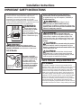 3
3
-
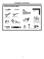 4
4
-
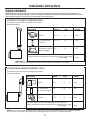 5
5
-
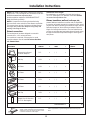 6
6
-
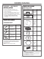 7
7
-
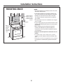 8
8
-
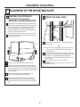 9
9
-
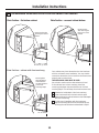 10
10
-
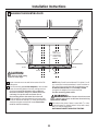 11
11
-
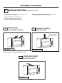 12
12
-
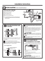 13
13
-
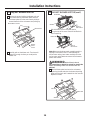 14
14
-
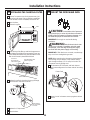 15
15
-
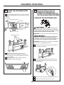 16
16
-
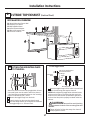 17
17
-
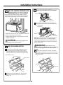 18
18
-
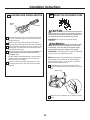 19
19
-
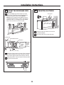 20
20
-
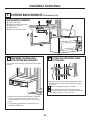 21
21
-
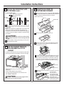 22
22
-
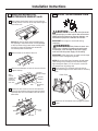 23
23
-
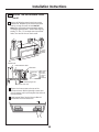 24
24
-
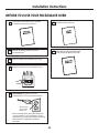 25
25
-
 26
26
-
 27
27
-
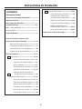 28
28
-
 29
29
-
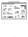 30
30
-
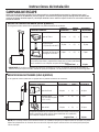 31
31
-
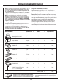 32
32
-
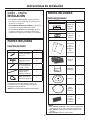 33
33
-
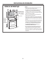 34
34
-
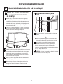 35
35
-
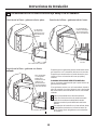 36
36
-
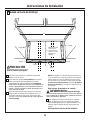 37
37
-
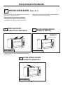 38
38
-
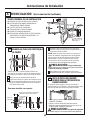 39
39
-
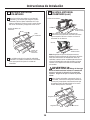 40
40
-
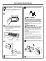 41
41
-
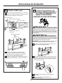 42
42
-
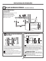 43
43
-
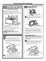 44
44
-
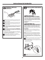 45
45
-
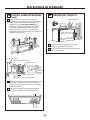 46
46
-
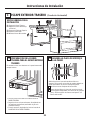 47
47
-
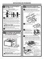 48
48
-
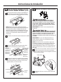 49
49
-
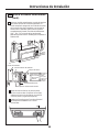 50
50
-
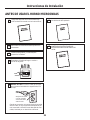 51
51
-
 52
52


GE RVM5160DHBB Manual de usuario
- Categoría
- Microondas
- Tipo
- Manual de usuario
en otros idiomas
- English: GE RVM5160DHBB User manual
Artículos relacionados
-
GE JVM3160 Guía de instalación
-
Hotpoint RVM5160DH2CC Guía de instalación
-
GE Appliances JVM3160DFCC Guía de instalación
-
GE PVM9005DJWW Guía de instalación
-
-
GE JVM3150DFBB Guía de instalación
-
GE PVM9179BLTS Guía de instalación
-
GE Appliances PNM9196SFSS Guía de instalación
-
GE 1067756 Guía de instalación
-