Bolens 13W1762F065 El manual del propietario
- Categoría
- Cortadoras de césped
- Tipo
- El manual del propietario
Este manual también es adecuado para

MTD LLC, P.O. BOX 361131 CLEVELAND, OHIO 44136-0019
Printed In USA
Safe Operation Practices • Set-Up • Operation • Maintenance • Service • Troubleshooting • Warranty
WARNING
READ AND FOLLOW ALL SAFETY RULES AND INSTRUCTIONS IN THIS MANUAL
BEFORE ATTEMPTING TO OPERATE THIS MACHINE.
FAILURE TO COMPLY WITH THESE INSTRUCTIONS MAY RESULT IN PERSONAL INJURY.
OperatOr’s Manual
Model Series 760-770 Lawn Tractor
Form No. 769-08412
(November 1, 2012)

Customer Support
Please do NOT return the machine to the retailer or dealer without first contacting our Customer Support Department.
If you have difficulty assembling this product or have any questions regarding the controls, operation, or maintenance of
this machine, you can seek help from the experts. Choose from the options below:
◊ Visit us on the web at www.mtdproducts.com
See How-to Maintenance and Parts Installation Videos at www.mtdparts.com/KnowledgeCenter
◊ Call a Customer Support Representative at (800) 800-7310 or (330) 220-4683
◊ Write us at MTD LLC • P.O. Box 361131 • Cleveland, OH • 44136-0019
Thank you for purchasing a lawn tractor manufactured by MTD.
It was carefully engineered to provide excellent performance
when properly operated and maintained.
Please read this entire manual prior to operating the equipment.
It instructs you how to safely and easily set up, operate and
maintain your machine. Please be sure that you, and any other
persons who will operate the machine, carefully follow the
recommended safety practices at all times. Failure to do so could
result in personal injury or property damage.
All information in this manual is relative to the most recent
product information available at the time of printing. Review
this manual frequently to familiarize yourself with the machine,
its features and operation. Please be aware that this Operator’s
Manual may cover a range of product specifications for various
models. Characteristics and features discussed and/or illustrated
in this manual may not be applicable to all models. MTD
reserves the right to change product specifications, designs and
equipment without notice and without incurring obligation.
If applicable, the power testing information used to establish
the power rating of the engine equipped on this machine can be
found at www.opei.org or the engine manufacturer’s web site.
If you have any problems or questions concerning the machine,
phone your local authorized MTD service dealer or contact us
directly. MTD’s Customer Support telephone numbers, website
address and mailing address can be found on this page. We want
to ensure your complete satisfaction at all times.
Throughout this manual, all references to right and left side of the
machine are observed from the operating position
The engine manufacturer is responsible for all engine-related
issues with regards to performance, power-rating, specifications,
warranty and service. Please refer to the engine manufacturer’s
Owner’s/Operator’s Manual, packed separately with your
machine, for more information.
Thank You
Record Product Information
Before setting up and operating your new equipment, please
locate the model plate on the equipment and record the
information in the provided area to the right. You can locate the
model plate by looking beneath the seat. This information will
be necessary, should you seek technical support via our web site,
Customer Support Department, or with a local authorized service
dealer.
Model NuMber
Serial NuMber
To The Owner
1
2
Safe Operation Practices ........................................ 3
Assembly & Set-Up .................................................. 9
Controls & Features ................................................13
Operation ................................................................16
Maintenance & Adjustment ................................ 20
Service .................................................................... 24
Troubleshooting .................................................... 29
Replacement Parts ................................................ 30
Attachments & Accessories ...................................31
Emission Control Statement ................................. 33
Warranty ................................................................ 35
Spanish ................................................................... 36
Table of Contents

Important Safe Operation Practices
2
3
General Operation
1. Read, understand, and follow all instructions on the
machine and in the manual(s) before attempting to
assemble and operate. Keep this manual in a safe place for
future and regular reference and for ordering replacement
parts.
2. Be familiar with all controls and their proper operation.
Know how to stop the machine and disengage them
quickly.
3. Never allow children under 14 years of age to operate this
machine. Children 14 and over should read and understand
the instructions and safe operation practices in this manual
and on the machine and should be trained and supervised
by an adult.
4. Never allow adults to operate this machine without proper
instruction.
5. To help avoid blade contact or a thrown object injury,
keep bystanders, helpers, children and pets at least 75 feet
from the machine while it is in operation. Stop machine if
anyone enters the area.
6. Thoroughly inspect the area where the equipment is to be
used. Remove all stones, sticks, wire, bones, toys, and other
foreign objects which could be picked up and thrown by
the blade(s). Thrown objects can cause serious personal
injury.
7. Plan your mowing pattern to avoid discharge of material
toward roads, sidewalks, bystanders and the like. Also,
avoid discharging material against a wall or obstruction
which may cause discharged material to ricochet back
toward the operator.
8. Always wear safety glasses or safety goggles during
operation and while performing an adjustment or repair
to protect your eyes. Thrown objects which ricochet can
cause serious injury to the eyes.
9. Wear sturdy, rough-soled work shoes and close-fitting
slacks and shirts. Loose fitting clothes and jewelry can be
caught in movable parts. Never operate this machine in
bare feet or sandals.
10. Be aware of the mower and attachment discharge direction
and do not point it at anyone. Do not operate the mower
without the discharge cover or entire grass catcher in its
proper place.
11. Do not put hands or feet near rotating parts or under the
cutting deck. Contact with the blade(s) can amputate
hands and feet.
WARNING! This symbol points out important safety instructions which, if not followed,
could endanger the personal safety and/or property of yourself and others. Read and follow
all instructions in this manual before attempting to operate this machine. Failure to comply
with these instructions may result in personal injury.
When you see this symbol. HEED ITS WARNING!
DANGER! This machine was built to be operated according to the safe operation practices in
this manual. As with any type of power equipment, carelessness or error on the part of the
operator can result in serious injury. This machine is capable of amputating hands and feet
and throwing objects. Failure to observe the following safety instructions could result in
serious injury or death.
CALIFORNIA PROPOSITION 65
WARNING! Engine Exhaust, some of its constituents, and certain vehicle components
contain or emit chemicals known to State of California to cause cancer and birth defects
or other reproductive harm.
WARNING! Battery posts, terminals, and related accessories contain lead and lead
compounds, chemicals known to the State of California to cause cancer and reproductive
harm. Wash hands after handling

4 Section 2 — important Safe operation practiceS
12. A missing or damaged discharge cover can cause blade
contact or thrown object injuries.
13. Stop the blade(s) when crossing gravel drives, walks, or
roads and while not cutting grass.
14. Watch for traffic when operating near or crossing
roadways. This machine is not intended for use on any
public roadway.
15. Do not operate the machine while under the influence of
alcohol or drugs.
16. Mow only in daylight or good artificial light.
17. Never carry passengers.
18. Disengage blade(s) before shifting into reverse. Back up
slowly. Always look down and behind before and while
backing to avoid a back-over accident.
19. Slow down before turning. Operate the machine smoothly.
Avoid erratic operation and excessive speed.
20. Disengage blade(s), set parking brake, stop engine and wait
until the blade(s) come to a complete stop before removing
grass catcher, emptying grass, unclogging chute, removing
any grass or debris, or making any adjustments.
21. Never leave a running machine unattended. Always turn
off blade(s), place transmission in neutral, set parking
brake, stop engine and remove key before dismounting.
22. Use extra care when loading or unloading the machine into
a trailer or truck. This machine should not be driven up or
down ramp(s), because the machine could tip over, causing
serious personal injury. The machine must be pushed
manually on ramp(s) to load or unload properly.
23. Muffler and engine become hot and can cause a burn. Do
not touch.
24. Check overhead clearances carefully before driving under
low hanging tree branches, wires, door openings etc.,
where the operator may be struck or pulled from the
machine, which could result in serious injury.
25. Disengage all attachment clutches, depress the brake
pedal completely and shift into neutral before attempting
to start engine.
26. Your machine is designed to cut normal residential grass of
a height no more than 10”. Do not attempt to mow through
unusually tall, dry grass (e.g., pasture) or piles of dry leaves.
Dry grass or leaves may contact the engine exhaust and/
or build up on the mower deck presenting a potential fire
hazard.
27. Use only accessories and attachments approved for this
machine by the machine manufacturer. Read, understand
and follow all instructions provided with the approved
accessory or attachment.
28. Data indicates that operators, age 60 years and above, are
involved in a large percentage of riding mower-related
injuries. These operators should evaluate their ability
to operate the riding mower safely enough to protect
themselves and others from serious injury.
29. If situations occur which are not covered in this manual, use
care and good judgment. Contact your customer service
representative for assistance.
Slope Operation
Slopes are a major factor related to loss of control and tip-over
accidents which can result in severe injury or death. All slopes
require extra caution. If you cannot back up the slope or if you
feel uneasy on it, do not mow it.
For your safety, use the slope gauge included as part of this
manual to measure slopes before operating this machine on
a sloped or hilly area. If the slope is greater than 15 degrees as
shown on the slope gauge, do not operate this machine on that
area or serious injury could result.
Do:
1. Mow up and down slopes, not across. Exercise extreme
caution when changing direction on slopes.
2. Watch for holes, ruts, bumps, rocks, or other hidden
objects. Uneven terrain could overturn the machine. Tall
grass can hide obstacles.
3. Use slow speed. Choose a low enough speed setting so
that you will not have to stop or shift while on the slope.
Tires may lose traction on slopes even though the brakes
are functioning properly. Always keep machine in gear
when going down slopes to take advantage of engine
braking action.
4. Follow the manufacturer’s recommendations for wheel
weights or counterweights to improve stability.
5. Use extra care with grass catchers or other attachments.
These can change the stability of the machine.
6. Keep all movement on the slopes slow and gradual. Do
not make sudden changes in speed or direction. Rapid
engagement or braking could cause the front of the
machine to lift and rapidly flip over backwards which could
cause serious injury.
7. Avoid starting or stopping on a slope. If tires lose traction,
disengage the blade(s) and proceed slowly straight down
the slope.
Do Not:
1. Do not turn on slopes unless necessary; then, turn slowly
and gradually downhill, if possible.
2. Do not mow near drop-offs, ditches or embankments. The
mower could suddenly turn over if a wheel is over the edge
of a cliff, ditch, or if an edge caves in.
3. Do not try to stabilize the machine by putting your foot on
the ground.
4. Do not use a grass catcher on steep slopes.
5. Do not mow on wet grass. Reduced traction could cause
sliding.
6. Do not shift to neutral and coast downhill. Over-speeding
may cause the operator to lose control of the machine
resulting in serious injury or death.
7. Do not tow heavy pull behind attachments (e.g. loaded
dump cart, lawn roller, etc.) on slopes greater than 5
degrees. When going down hill, the extra weight tends
to push the tractor and may cause you to loose control
(e.g. tractor may speed up, braking and steering ability are
reduced, attachment may jack-knife and cause tractor to
overturn).

5Section 2 — important Safe operation practiceS
Children
1. Tragic accidents can occur if the operator is not alert to the
presence of children. Children are often attracted to the
machine and the mowing activity. They do not understand
the dangers. Never assume that children will remain where
you last saw them.
a. Keep children out of the mowing area and in
watchful care of a responsible adult other than the
operator.
b. Be alert and turn machine off if a child enters the
area.
c. Before and while backing, look behind and down for
small children.
d. Never carry children, even with the blade(s) shut off.
They may fall off and be seriously injured or interfere
with safe machine operation.
e. Use extreme care when approaching blind corners,
doorways, shrubs, trees or other objects that may
block your vision of a child who may run into the
path of the machine.
f. To avoid back-over accidents, always disengage
the cutting blade(s) before shifting into Reverse.
If equipped, the “Reverse Caution Mode” should
not be used when children or others are around.
g. Keep children away from hot or running engines.
They can suffer burns from a hot muffler.
h. Remove key when machine is unattended to
prevent unauthorized operation.
2. Never allow children under 14 years of age to operate this
machine. Children 14 and over should read and understand
the instructions and safe operation practices in this manual
and on the machine and should be trained and supervised
by an adult.
Towing
1. Tow only with a machine that has a hitch designed for
towing. Do not attach towed equipment except at the
hitch point.
2. Follow the manufacturers recommendation for weight
limits for towed equipment and towing on slopes.
3. Never allow children or others in or on towed equipment.
4. On slopes, the weight of the towed equipment may cause
loss of traction and loss of control.
5. Always use extra caution when towing with a machine
capable of making tight turns (e.g. “zero-turn” ride-on
mower). Make wide turns to avoid jack-knifing.
6. Travel slowly and allow extra distance to stop.
7. Do not shift to neutral and coast downhill.
Service
Safe Handling of Gasoline:
1. To avoid personal injury or property damage use extreme
care in handling gasoline. Gasoline is extremely
flammable and the vapors are explosive. Serious
personal injury can occur when gasoline is spilled on
yourself or your clothes which can ignite. Wash your skin
and change clothes immediately.
a. Use only an approved gasoline container.
b. Never fill containers inside a vehicle or on a truck
or trailer bed with a plastic liner. Always place
containers on the ground away from your vehicle
before filling.
c. When practical, remove gas-powered equipment
from the truck or trailer and refuel it on the ground.
If this is not possible, then refuel such equipment on
a trailer with a portable container, rather than from a
gasoline dispenser nozzle.
d. Keep the nozzle in contact with the rim of the fuel
tank or container opening at all times until fueling is
complete. Do not use a nozzle lock-open device.
e. Extinguish all cigarettes, cigars, pipes and other
sources of ignition.
f. Never fuel machine indoors.
g. Never remove gas cap or add fuel while the engine
is hot or running. Allow engine to cool at least two
minutes before refueling.
h. Never over fill fuel tank. Fill tank to no more than ½
inch below bottom of filler neck to allow space for
fuel expansion.
i. Replace gasoline cap and tighten securely.
j. If gasoline is spilled, wipe it off the engine and
equipment. Move machine to another area. Wait 5
minutes before starting the engine.
k. To reduce fire hazards, keep machine free of grass,
leaves, or other debris build-up. Clean up oil or fuel
spillage and remove any fuel soaked debris.
l. Never store the machine or fuel container inside
where there is an open flame, spark or pilot light
as on a water heater, space heater, furnace, clothes
dryer or other gas appliances.
m. Allow a machine to cool at least five minutes before
storing.
General Service
1. Never run an engine indoors or in a poorly ventilated area.
Engine exhaust contains carbon monoxide, an odorless,
and deadly gas.
2. Before cleaning, repairing, or inspecting, make certain the
blade(s) and all moving parts have stopped. Disconnect the
spark plug wire and ground against the engine to prevent
unintended starting.

6 Section 2 — important Safe operation practiceS
3. Periodically check to make sure the blades come to
complete stop within approximately (5) five seconds after
operating the blade disengagement control. If the blades
do not stop within the this time frame, your machine
should be serviced professionally by an authorized MTD
Service Dealer.
4. Check brake operation frequently as it is subjected to wear
during normal operation. Adjust and service as required.
5. Check the blade(s) and engine mounting bolts at frequent
intervals for proper tightness. Also, visually inspect blade(s)
for damage (e.g., excessive wear, bent, cracked). Replace
the blade(s) with the original equipment manufacturer’s
(O.E.M.) blade(s) only, listed in this manual. “Use of parts
which do not meet the original equipment specifications
may lead to improper performance and compromise
safety!”
6. Mower blades are sharp. Wrap the blade or wear gloves,
and use extra caution when servicing them.
7. Keep all nuts, bolts, and screws tight to be sure the
equipment is in safe working condition.
8. Never tamper with the safety interlock system or other
safety devices. Check their proper operation regularly.
9. After striking a foreign object, stop the engine, disconnect
the spark plug wire(s) and ground against the engine.
Thoroughly inspect the machine for any damage. Repair
the damage before starting and operating.
10. Never attempt to make adjustments or repairs to the
machine while the engine is running.
11. Grass catcher components and the discharge cover are
subject to wear and damage which could expose moving
parts or allow objects to be thrown. For safety protection,
frequently check components and replace immediately
with original equipment manufacturer’s (O.E.M.) parts only,
listed in this manual. “Use of parts which do not meet the
original equipment specifications may lead to improper
performance and compromise safety!”
12. Do not change the engine governor settings or over-speed
the engine. The governor controls the maximum safe
operating speed of the engine.
13. Maintain or replace safety and instruction labels, as
necessary.
14. Observe proper disposal laws and regulations for gas, oil,
etc. to protect the environment.
15. According to the Consumer Products Safety Commission
(CPSC) and the U.S. Environmental Protection Agency (EPA),
this product has an Average Useful Life of seven (7) years,
or 270 hours of operation. At the end of the Average Useful
Life have the machine inspected annually by an authorized
service dealer to ensure that all mechanical and safety
systems are working properly and not worn excessively.
Failure to do so can result in accidents, injuries or death.
Do not modify engine
To avoid serious injury or death, do not modify engine in any
way. Tampering with the governor setting can lead to a runaway
engine and cause it to operate at unsafe speeds. Never tamper
with factory setting of engine governor.
Notice Regarding Emissions
Engines which are certified to comply with California and federal
EPA emission regulations for SORE (Small Off Road Equipment)
are certified to operate on regular unleaded gasoline, and
may include the following emission control systems: Engine
Modification (EM), Oxidizing Catalyst (OC), Secondary Air
Injection (SAI) and Three Way Catalyst (TWC) if so equipped.
When required, models are equipped with low permeation fuel
lines and fuel tanks for evaporative emission control. California
models may also include a carbon canister. Please contact
Customer Support for information regarding the evaporative
emission control configuration for your model.
Spark Arrestor
WARNING! This machine is equipped with an
internal combustion engine and should not be used
on or near any unimproved forest-covered,
brushcovered or grass-covered land unless the
engine’s exhaust system is equipped with a spark
arrestor meeting applicable local or state laws (if
any).
If a spark arrestor is used, it should be maintained in effective
working order by the operator. In the State of California the
above is required by law (Section 4442 of the California Public
Resources Code). Other states may have similar laws. Federal laws
apply on federal lands.
A spark arrestor for the muffler is available through your
nearest engine authorized service dealer or contact the service
department, P.O. Box 361131 Cleveland, Ohio 44136-0019.
WARNING! Your Responsibility—Restrict the use of this power machine to persons who read, understand and
follow the warnings and instructions in this manual and on the machine.
SAVE THESE INSTRUCTIONS!

7Section 2 — important Safe operation practiceS
Safety Symbols
This page depicts and describes safety symbols that may appear on this product. Read, understand, and follow all instructions on the
machine before attempting to assemble and operate.
Symbol Description
READ THE OPERATOR’S MANUAL(S)
Read, understand, and follow all instructions in the manual(s) before attempting to
assemble and operate
DANGER— ROTATING BLADES
Never carry passengers. Never carry children, even with the blades off.
DANGER— ROTATING BLADES
Always look down and behind before and while backing to avoid a back-over accident.
WARNING— ROTATING BLADES
Do not put hands or feet near rotating parts or under the cutting deck. Contact with the
blade(s) can amputate hands and feet.
WARNING—THROWN OBJECTS
This machine may pick up and throw and objects which can cause serious personal injury.
WARNING—THROWN OBJECTS
This machine may pick up and throw and objects which can cause serious personal injury.
BYSTANDERS
Keep bystanders, helpers, children and pets at least 75 feet from the machine while it is in
operation.
WARNING— SLOPE OPERATION
Do not operate this machine on a slope greater than 15 degrees.
WARNING— HOT SURFACE
Engine parts, especially the muffler, become extremely hot during operation. Allow engine
and muffler to cool before touching.
DANGER — ROTATING BLADES
To reduce the risk of injury, keep hands and feet away. Do not operate unless discharge cover
or grass catcher is in its proper place. If damaged, replace immediately.
WARNING— TOWING
Avoid jack-knifing when towing, go slow and make wide turns.

8 Section 2 — important Safe operation practiceS
(OK) (TOO STEEP)
USE THIS SLOPE GAUGE TO DETERMINE
IF A SLOPE IS TOO STEEP FOR SAFE OPERATION!
To check the slope, proceed as follows:
1. Remove this page and fold along the dashed line.
2. Locate a vertical object on or behind the slope (e.g. a pole, building, fence, tree, etc.)
3. Align either side of the slope gauge with the object (See Figure 1 and Figure 2 ).
4. Adjust gauge up or down until the left corner touches the slope (See Figure 1 and Figure 2).
5. If there is a gap below the gauge, the slope is too steep for safe operation (See Figure 2 above).
15° dashed line
Slope Gauge
Figure 2Figure 1
15° Slope
15° Slope
WARNING! Slopes are a major factor related to tip-over and roll-over accidents which can result in severe injury or death.
Do not operate machine on slopes in excess of 15 degrees. All slopes require extra caution. If you cannot back up the slope
or if you feel uneasy on it, do not mow it. Always mow up and down slopes, never across the face of slopes.

3
9
Tractor Set-Up
NOTE: This Operators Manual covers a range of product
specifications for various models. Characteristics and features
discussed and/or illustrated in this manual may not be applicable
to all models. MTD LLC reserves the right to change product
specifications, designs and equipment without notice and
without incurring obligation.
Connecting the Battery Cables
CALIFORNIA PROPOSITION 65 WARNING:
Battery posts, terminals, and related accessories
contain lead and lead compounds, chemicals known
to the State of California to cause cancer and
reproductive harm. Wash hands after handling.
CAUTION: When attaching battery cables, always
connect the POSITIVE (Red) wire to its terminal first,
followed by the NEGATIVE (Black) wire.
For shipping reasons, both battery cables on your equipment
may have been left disconnected from the terminals at the
factory. To connect the battery cables, proceed as follows:
NOTE: The positive battery terminal is marked Pos. (+). The
negative battery terminal is marked Neg. (–).
1. Remove the plastic cover, if present, from the positive battery
terminal and attach the red cable to the positive battery
terminal (+) with the bolt and hex nut. See Figure 3-1.
Figure 3-1
2. Remove the plastic cover, if present, from the negative
battery terminal and attach the black cable to the negative
battery terminal (–) with the bolt and hex nut. See Figure
3-1.
3. Position the red rubber boot over the positive battery
terminal to help protect it from corrosion.
NOTE: If the battery is put into service after the date shown
on top/side of battery, charge the battery as instructed in the
Maintenance section your Operator’s Manual prior to operating
the tractor.
Shipping Brace Removal
WARNING! Make sure the riding mower’s engine is
off, remove the ignition key, and set the parking
brake before removing the shipping brace. Refer to
the Controls and Features section for instructions on
how to set the parking brake.
• Locate the shipping brace, if present, and accompanying
warning tag found on the right side of the mower, between
the discharge chute and the cutting deck. See Figure 3-2.
Figure 3-2
• Place the deck lift lever in the highest cutting position.
Refer to Setting the Cutting Height in the Operation
section of this manual.
• While pushing the discharge chute towards the machine
with your left hand, remove the shipping brace with your
right hand by grasping it between your thumb and index
finger and rotating it clockwise.
WARNING! The shipping brace, used for
packaging purposes only, must be removed and
discarded before operating your riding mower.
WARNING! The mowing deck is capable of
throwing objects. Failure to operate the riding
mower without the discharge cover in the proper
operating position could result in serious personal
injury and/or property damage.
Assembly & Set-Up

10 Section 3— ASSembly & Set-Up
Attaching The Seat
If the seat for your tractor was not attached at the factory, refer
to the following steps.
NOTE: For shipping reasons, seats are either fastened to the
tractor seat’s pivot bracket with a plastic tie, or mounted
backward to the pivot bracket. In either case, free the seat from
its shipping position and remove the adjustment knob from the
bottom of seat before proceeding with the instructions below.
1. As already instructed, remove the seat adjustment knob
installed by the factory in the bottom of the seat. See “a” in
Figure 3-5.
2. Align the seat over the seat pivot bracket as shown in
Figure 3-5 and fit the seat onto the pivot bracket inserting
the two tabs on the seat bottom into the slots on the pivot
bracket.
3. Slide the seat rearward in the seat pivot bracket (c),
lining up the center rear slot in the pivot bracket with the
remaining hole in the seat’s base. See Figure 3-6.
Note: Be certain the two seat tabs engauge the pivot
bracket as shown in the bottom inset of Figure 3-6.
4. Select desired position for the seat, and secure with the
adjustment knob removed earlier (d in Figure 3-6).
b
a
Figure 3-5
Attaching The Steering Wheel
If the steering wheel for your tractor did not come attached, the
hardware for attaching it has been packed within the steering
wheel, beneath the steering wheel cap. Carefully pry off the
steering wheel cap and remove the hardware.
1. With the wheels of the tractor pointing straight forward,
place the steering wheel over the steering shaft.
2. Place the washer (with the cupped side down) over the
steering wheel and secure with the hex bolt. See Figure 3-3.
Figure 3-3
3. Place the steering wheel cap over the center of the steering
wheel and push downward until it “clicks” into place.
Attaching The Dash Collar (If equipped)
If the tractor’s dash collar did not come attached from the
factory, the screws for attaching it can be found in either side of
the dash console. Remove the two screws from the console and
secure the dash collar as illustrated in Figure 3-4.
Figure 3-4

11Section 3 — ASSembly & Set-Up
5. To adjust the position of the seat, remove the adjustment
knob on the bottom of the seat. Slide the seat forward or
backward as desired. Reinstall the adjustment knob. See
Figure 3-6.
c
d
Figure 3-6
Mulch Plug (if equipped)
On tractor models so equipped, a mulch plug can be found
within the cutting deck’s discharge opening.
NOTE: Refer to Mulching in the “Operation” section of this
manual for more detailed information.
If you’d prefer to operate the cutting deck without mulching,
simply remove the mulch plug by unthreading the plastic
wing nut which fastens it to the cutting deck. This will allow
the clippings to discharge out of the discharge opening during
operation. See Figure 3-7.
Figure 3-7
Note: See the Attachments & Accessories section if you would
like information regarding adding a mulching system for your
model of tractor.
Tire Pressure
WARNING! Maximum tire pressure under any
circumstances is 30 psi. Equal tire pressure should be
maintained at all times. Never exceed the maximum
inflation pressure shown on the sidewall of the tire.
The recommended operating tire pressure is:
• Approximately 10 psi for the rear tires
• Approximately 14 psi for the front tires
IMPORTANT: Refer to the tire sidewall for exact tire
manufacturer’s recommended or maximum psi. Do not
overinflate. Uneven tire pressure could cause the cutting deck to
mow unevenly.
Gas and Oil Fill-up
OIL
IMPORTANT: Your tractor is shipped with motor oil in the
engine. However, you MUST check the oil level before operating.
Be careful not to overfill.
Service and check the engine oil as instructed in the separate
Engine Operator/Owner Manual packed with your tractor. Read
the instructions carefully.
GASOLINE
The gasoline tank is located under the hood. Do not overfill.
WARNING! Use extreme care when handling
gasoline. Gasoline is extremely flammable and the
vapors are explosive. Never fuel machine indoors or
while the engine is hot or running. Extinguish
cigarettes, cigars, pipes, and other sources of ignition.
NOTE : Purchase gasoline in small quantities. Do not use gasoline
left over from the previous season, to minimize gum deposits in
the fuel system.
• This engine is certified to operate on unleaded gasoline.
For best results, fill the fuel tank with only clean, fresh,
unleaded gasoline with a pump sticker octane rating of 87
or higher.
• Gasohol (up to 10% ethyl alcohol, 90% unleaded gasoline
by volume) is an approved fuel. Other gasoline/alcohol
blends, such as E85, are not approved.
• Methyl Tertiary Butyl Ether (MTBE) and unleaded gasoline
blends (up to a maximum of 15% MTBE by volume) are
approved fuels. Other gasoline/ether blends are not
approved.
• Fill fuel tank outdoors or in well-ventilated area.
• Do not overfill fuel tank. Fill tank to no more than 1/2
inch below bottom of filler neck to allow space for fuel
expansion.
• Never remove gas cap or add fuel while the engine is hot or
running. Allow engine to cool at least two minutes before
refueling.

12 Section 3— ASSembly & Set-Up
• If gasoline is spilled, wipe it off the engine and equipment.
Move machine to another area. Wait 5 minutes before
starting the engine.
To Add Gasoline
1. Turn the engine off and let engine cool at least 2 minutes
before removing the fuel cap. The gasoline tank is located
under the hood. Remove the fuel cap by turning it
counterclockwise.
2. Fill the fuel tank with gasoline. Use only clean, fresh (no
more than 30 days old), unleaded gasoline. Fill tank to no
more than 1/2 inch below bottom of filler neck to allow
space for fuel expansion. See Figure 3-8.
3. Reinstall the fuel cap.
IMPORTANT: Do not overfill the tank. Fill tank to no more
than 1/2 inch below bottom of filler neck to allow space for fuel
expansion. See Figure 3-8.
Figure 3-8
Setting the Deck Gauge Wheels (if so equipped)
Move the tractor on a firm and level surface, preferably
pavement, and proceed as follows
1. Select the height position of the cutting deck by placing
the deck lift lever in the normally desired mowing height
setting (any of the six different cutting height notches on the
right fender).
2. Check the gauge wheels for contact or excessive clearance
with the surface below. The deck gauge wheels should
have between ¼-inch and ½-inch clearance above the
ground as follows:
If the gauge wheels have excessive clearance or contact with the
surface, adjust as follows:
a. Raise the deck lift handle to its highest setting.
b. Remove the gauge wheels by removing the lock
nuts and shoulder screws which secure them to the
deck. See Figure 3-9.
Figure 3-9
c. Place the deck lift lever in the desired mowing
height setting.
d. Reinsert the shoulder screw (with each gauge
wheel) into the index hole that leaves approximately
½-inch between the bottom of the wheel and the
pavement.
Refer to Leveling the Deck in the Maintenance section of this
manual for more detailed instructions regarding various deck
adjustments.

Controls and Features
4
13
Speed Control &
Parking Brake Lever
Ammeter
(On some models)
Clutch/Brake Pedal
Shift Lever
Throttle/Choke Lever
Deck Lift Lever
PTO (Blade Engage) Lever
Ignition Switch
Module
Figure 4-1
Lawn Tractor controls and features are illustrated in Figure 4-1 and described on the following pages.
WARNING! Read and follow all safety rules and instructions in this manual, including the entire Operation section,
before attempting to operate this machine. Failure to comply with all safety rules and instructions may result in personal
injury.

Throttle Control Lever
The throttle control lever is located on the left side
of the tractor’s dash panel. This lever controls the
speed of the engine and, on some models, when
pushed all the way forward, the choke control
also. When set in a given position, the throttle will
maintain a uniform engine speed.
IMPORTANT: When operating the tractor with
the cutting deck engaged, be certain that the
throttle lever is always in the FAST (rabbit) position.
Choke Control
On some models, moving the throttle lever all the
way forward activates the engine’s choke control.
On all other models, the choke control can be
found on the dash panel and is activated by pulling
the knob outward. Activating the choke control
closes the choke plate on the carburetor and aids
in starting the engine. Refer to Starting The Engine
in the Operation section of this manual for detailed
starting instructions.
Ignition Switch
Your new lawn tractor will have one of the following ignition
switches. Use Fig. 4-3 to identify which switch your machine
utilizes and follow these instructions for proper operation.
3-Position Ignition Switch
The ignition switch is activated to start the engine. Insert key
into the ignition switch and turn clockwise to the START position.
Release the key into the ON position once engine has fired. See
Figure 4-2A. The engine will run with the headlights on.
To stop the engine, turn the ignition key counterclockwise to the
OFF position. See Figure 4-2A.
4-Position Ignition Switch
The ignition switch is activated to start the engine. Insert key
into the ignition switch and turn clockwise to the START position.
Release the key into the ON position once engine has fired.
See Figure 4-2B. The engine will run with the headlights off in
this position. To activate the headlights, turn the key one more
position to the left. The engine will continue to run with the
headlights on.
To stop the engine, turn the ignition key counterclockwise to the
OFF position. See Figure 4-2B.
Ignition Switch Module
To start the engine, insert the key into the ignition switch and
turn clockwise to the START position. Release the key into the
NORMAL MOWING MODE position once the engine has fired. The
headlights will be activated in the Normal (and Reverse Caution
Modes).
To stop the engine, turn the ignition key counterclockwise to the
OFF position. See Fig. 4-3C.
WARNING! Never leave a running machine
unattended. Always disengage PTO, move shift lever
into neutral position, set parking brake, stop engine
and remove key to prevent unintended starting.
IMPORTANT: Prior to operating the tractor, refer to both Safety
Interlock Switches and Starting The Engine in the Operation
section of this manual for detailed instructions regarding the
Ignition Switch Module and operating the tractor in REVERSE
CAUTION MODE.
Off
On/Lights
Start
Off
On/Lights
Start
On
Stop
Position
Normal
Mowing
Start
Position
Reverse
Caution Mode
A
B
C
Figure 4-2
14 Section 4 — controlS and FeatureS

Speed Control Lever
The speed control lever, located on the left side of
the tractor’s dash console, allows you to regulate
the ground speed of the lawn tractor. To use,
depress the clutch-brake pedal and move the
lever out of the parking brake notch and forward
to increase the tractor’s ground speed. When a
desired speed has been reached, release the lever
into an appropriate notch to maintain that speed.
To slow the tractor’s ground speed, depress the
clutch-brake pedal and move the speed control
lever rearward and release it into a notch.
NOTE: Lawn tractors vary by model and are
available with either a 6- or 7-speed control lever.
Deck Lift Lever
Found on your tractor’s right fender, the deck lift lever is used to
change the height of the cutting deck. To use, move the lever to
the left, then place in the notch best suited for your application.
PTO (Blade Engage) Lever
Found on the tractor’s right fender, the PTO (blade
engage) lever is used to engage power to the cutting
deck or other (separately available) attachments.
To operate, move the lever all the way forward.
Moving the lever all the way rearward into the PTO
OFF position disengages power to the cutting deck/
attachment.
NOTE: The PTO (blade engage) lever must be in the
disengaged (PTO OFF) position when starting the
engine.
Clutch-Brake Pedal
The clutch-brake pedal is located on the left side of the lawn
tractor, along the running board. Depress the clutch-brake pedal
part way down when slowing the tractor by changing speeds
(Refer to Speed Control Lever). Depress the pedal all the way down
to engage the disc brake and bring the tractor to a complete
stop.
NOTE: The pedal must be depressed to start the engine. Refer to
Safety Interlock Switches in the Operation section of this manual.
Parking Brake
To set the parking brake, fully depress the clutch-
brake pedal. Move the speed control lever all the
way down and into the parking brake position.
Release the clutch-brake pedal to allow the parking
brake to engage.
To release the parking brake, depress the clutch-
brake pedal and move the speed control lever out
of the notches to the desired position. Release the
speed control lever and the clutch-brake pedal.
NOTE: The parking brake must be set if the
operator leaves the seat with the engine running or
the engine will automatically shut off.
Shift Lever
The shift lever is located on the left side of the
fender and has three positions, FORWARD,
NEUTRAL and REVERSE. The brake pedal must be
depressed and the tractor must not be in motion
when the moving shift lever. See Figure 4-3.
IMPORTANT: Never force the shift lever. Doing so may result in
serious damage to the tractor’s transmission.
Figure 4-3
RUN
PARK
BRAKE
ON
PARK
BRAKE
OFF
15Section 4 — controlS and FeatureS

Operation
5
16
Safety Interlock Switches
This tractor is equipped with a safety interlock system for the
protection of the operator. If the interlock system should ever
malfunction, do not operate the tractor. Contact an authorized
MTD service dealer.
• The safety interlock system prevents the engine from
cranking or starting unless the parking brake is engaged,
and the PTO (Blade Engage) lever is in the disengaged (OFF)
position.
• The engine will automatically shut off if the operator leaves
the seat before engaging the parking brake.
• The engine will automatically shut off if the operator leaves
the tractor’s seat with the PTO (Blade Engage) lever in the
engaged (ON) position, regardless of whether the parking
brake is engaged.
Models without Reverse Caution Mode
• The engine will automatically shut off if the PTO (Blade
Engage) lever is moved into the engaged (ON) position with
the shift lever in Reverse.
Models with Reverse Caution Mode
• With the ignition key in the NORMAL MOWING position,
the engine will automatically shut off if the PTO (Blade
Engage) lever is moved into the engaged (ON) position with
the shift lever in Reverse.
WARNING! Do not operate the tractor if the
interlock system is malfunctioning. This system was
designed for your safety and protection.
Reverse Caution Mode
(Models equipped with ignition switch module)
WARNING! Use extreme caution while operating
the tractor in the REVERSE CAUTION MODE. Always
look down and behind before and while backing. Do
not operate the tractor when children or others are
around. Stop the tractor immediately if someone
enters the area.
The REVERSE CAUTION MODE position of the key switch
module allows the tractor to maneuver in reverse with the blades
(PTO) engaged.
IMPORTANT: Mowing in reverse is not recommended.
To use the REVERSE CAUTION MODE:
IMPORTANT: The operator MUST be seated in the tractor seat.
1. Start the engine as instructed in the Operation section of
this manual.
2. Turn the key from the NORMAL MOWING (Green) position
to the REVERSE CAUTION MODE (Yellow) position of the key
switch module. See Figure 5-1.
Stop
position
Start
position
Indicator
Light
Reverse
Push
Button
Normal
Driving
Mode
Reverse
Caution
Mode
Position
Figure 5-1

17Section 5 — operation
3. Depress the REVERSE PUSH BUTTON (Orange, Triangular
Button) at the top, right corner of the key switch module.
The red indicator light at the top, left corner of the key
switch module will be ON while activated. See Figure 5-1.
4. Once activated (indicator light ON), the tractor can be driven
in reverse with the cutting blades (PTO) engaged.
5. Always look down and behind before and while backing to
make sure no children are around.
6. After resuming forward motion, return the key to the
NORMAL MOWING position.
IMPORTANT: The REVERSE CAUTION MODE will remain
activated until:
a. The key is placed in either the NORMAL MOWING
position or STOP position.
b. The operator engages the parking brake by fully
depressing the clutch-brake pedal and holding it
down while moving the speed control lever into the
PARK BRAKE position.
Engaging the Parking Brake
To engage the parking brake:
1. Fully depress the clutch-brake pedal and hold it down with
your foot.
2. Move the speed control lever all the way down and into the
parking brake position.
3. Release the clutch-brake pedal to allow the parking brake
to engage.
To release the parking brake:
1. Depress the clutch-brake pedal and move the speed
control lever out of the parking brake position and into a
desired speed.
Setting the Cutting Height
1. Select the height position of the cutting deck by placing
the deck lift lever in any of the six different cutting height
notches on the right side of the fender.
2. Adjust the deck wheels as instructed in the Assembly & Set-
Up section earlier in this manual, if equipped, so that they
are between ¼-inch and ½-inch above the ground when
the tractor is on a smooth, flat surface such as a driveway.
WARNING! Keep hands and feet away from the
discharge opening of the cutting deck.
NOTE: On models so equipped, the deck wheels are an anti-scalp
feature of the deck and are not designed to support the weight
of the cutting deck. Refer to Leveling in the Maintenance section
of this manual for more detailed instructions regarding various
deck adjustments.
Starting the Engine
WARNING! Do not operate the tractor if the
interlock system is malfunctioning. This system was
designed for your safety and protection.
NOTE: Refer to the Gasoline and Oil fill-up instructions in the
separate Engine Operator’s manual included with this tractor.
1. Insert the tractor key into the ignition switch.
2. Place the PTO (Blade Engage) lever in the disengaged (OFF)
position.
3. Engage the tractor’s parking brake.
4. Activate the choke control.
5. Turn the ignition key clockwise to the START position. After
the engine starts, release the key. It will return to the ON (or
Normal Mowing) position.
CAUTION: Do NOT hold the key in the START
position for longer than ten seconds at a time. Doing
so may cause damage to your engine’s electric
starter.
6. After the engine starts, deactivate the choke control and
place the throttle control in the FAST position.
NOTE: Do NOT leave the choke control on while operating the
tractor. Doing so will result in a “rich” fuel mixture and cause the
engine to run poorly.
Stopping the Engine
WARNING! If you strike a foreign object, stop the
engine, disconnect the spark plug wire(s) and
ground against the engine. Thoroughly inspect the
machine for any damage. Repair the damage before
restarting and operating
1. If the blades are engaged, place the PTO (Blade Engage)
lever in the disengaged (OFF) position.
2. Turn the ignition key counterclockwise to the STOP
position.
3. Remove the key from the ignition switch to prevent
unintended starting.

18 Section 5— operation
Driving The Tractor
WARNING! Avoid sudden starts, excessive speed
and sudden stops.
WARNING! Do not leave the seat of the tractor
without first placing the PTO (Blade Engage) lever in
the disengaged (OFF) position, depressing the brake
pedal and engaging the parking brake. If leaving
the tractor unattended, also turn the ignition key off
and remove the key.
WARNING! Always look down and behind before
and while backing up to avoid a back-over accident.
1. Depress the brake pedal to release the parking brake and
let the pedal up.
2. Move the throttle lever into the FAST (rabbit) position.
3. Place the shift lever in either the FORWARD or REVERSE
position.
IMPORTANT: Do NOT use the shift lever to change the
direction of travel when the tractor is in motion. Always use
the brake pedal to bring the tractor to a complete stop before
shifting.
4. Release the parking brake by depressing the clutch-brake
pedal and positioning the speed control lever in desired
position.
IMPORTANT: First-time operators should use speed positions 1
or 2. Become completely familiar with the tractor’s operation and
controls before operating the tractor in higher speed positions.
5. Release clutch-brake pedal slowly to put unit into motion.
6. The lawn tractor is brought to a stop by depressing the
clutch-brake pedal.
NOTE: When operating the unit initially, there will be little
difference between the highest two speeds until after the belts
have seated themselves into the pulleys during the break-in
period.
WARNING! Before leaving the operator’s position
for any reason, disengage the blades, place the shift
lever in neutral, engage the parking brake, shut
engine off and remove the key.
IMPORTANT: When stopping the tractor for any reason while
on a grass surface, always:
1. Place the shift lever in neutral,
2. Engage the parking brake,
3. Shut engine off and remove the key. Doing so will minimize
the possibility of having your lawn ‘‘browned’’ by hot
exhaust from your tractor’s running engine.
If unit stalls with speed control in high speed, or if unit will
not operate with speed control lever in a low speed position,
proceed as follows:
1. Place shift lever in NEUTRAL.
2. Restart engine.
3. Place speed control lever in highest speed position.
4. Release clutch-brake pedal fully.
5. Depress clutch-brake pedal.
6. Place speed control lever in desired position.
7. Place shift lever in either FORWARD or REVERSE, and follow
normal operating procedures.
Driving On Slopes
Refer to the SLOPE GAUGE in the Important Safe Operation
Practices section of the manual to help determine slopes where
you may operate the tractor safely.
WARNING! Do not mow on inclines with a slope in
excess of 15 degrees (a rise of approximately 2-1/2 feet
every 10 feet). The tractor could overturn and cause
serious injury.
• Mow up and down slopes, NEVER across.
• Exercise extreme caution when changing direction on
slopes.
• Watch for holes, ruts, bumps, rocks, or other hidden
objects. Uneven terrain could overturn the machine. Tall
grass can hide obstacles.
• Avoid turns when driving on a slope. If a turn must be
made, turn down the slope. Turning up a slope greatly
increases the chance of a roll over.
• Avoid stopping when driving up a slope. If it is necessary
to stop while driving up a slope, start up smoothly and
carefully to reduce the possibility of flipping the tractor
over backward.
Engaging the Blades
Engaging the PTO (Blade Engage) transfers power to the cutting
deck or other (separately available) attachments. To engage the
blades, proceed as follows:
1. Move the throttle control lever to the FAST (rabbit)
position.
2. Grasp the PTO (Blade Engage) lever and pivot it all the way
forward into the engaged (ON) position.
3. Keep the throttle lever in the FAST (rabbit) position for the
most efficient use of the cutting deck or other (separately
available) attachments.
Models with Reverse Caution Mode:
The engine will automatically shut off if the PTO is engaged with
the shift lever in position for reverse travel with the ignition key
in the NORMAL MOWING position.
Models without Reverse Caution Mode:
The PTO (Blade Engage) lever must be in the disengaged (OFF)
position when starting the engine, when traveling in reverse, and
if the operator leaves the seat. Refer to Safety Interlock Switches
in the Operation section of this manual.
Using the Deck Lift Lever
To raise the cutting deck, move the deck lift lever to the left, then
place it in the notch best suited for your application. Refer to
Setting The Cutting Height earlier in this section.

19Section 5 — operation
Mowing
WARNING! To help avoid blade contact or a
thrown object injury, keep bystanders, helpers,
children and pets at least 75 feet from the machine
while it is in operation. Stop machine if anyone
enters the area.
The following information will be helpful when using the cutting
deck with your tractor:
WARNING! Plan your mowing pattern to avoid
discharge of materials toward roads, sidewalks,
bystanders and the like. Also, avoid discharging
material against a wall or obstruction which may
cause discharged material to ricochet back toward
the operator.
• Do not mow at high ground speed, especially if a mulch kit
or grass collector is installed.
• For best results it is recommended that the first two laps be
cut with the discharge thrown towards the center. After the
first two laps, reverse the direction to throw the discharge
to the outside for the balance of cutting. This will give a
better appearance to the lawn.
• Do not cut the grass too short. Short grass invites weed
growth and yellows quickly in dry weather.
• Mowing should always be done with the engine at full throttle.
• Under heavier conditions it may be necessary to go back
over the cut area a second time to get a clean cut.
• Do NOT attempt to mow heavy brush and weeds and
extremely tall grass. Your tractor is designed to mow lawns,
NOT clear brush.
• Keep the blades sharp and replace the blades when worn.
Refer to Cutting Blades in the Service section of this manual
for proper blade sharpening instructions.
Mulching
Select models come equipped with a mulch kit which
incorporates special blades, already standard on the tractor, in a
process of recirculating grass clippings repeatedly beneath the
cutting deck. The ultra-fine clippings are then forced back into
the lawn where they act as a natural fertilizer.
Observe the following points for the best results when mulching:
• Never attempt to mulch if the lawn is damp. Wet grass
tends to stick to the underside of the cutting deck
preventing proper mulching of the clippings.
• Do NOT attempt to mulch more than 1/3 the total height of
the grass or approximately 1-1/2 inches. Doing so will cause
the clippings to clump up beneath the deck and not be
mulched effectively.
• Maintain a slow ground speed to allow the grass clippings
more time to effectively be mulched.
• Always position the throttle control lever in the FAST
(rabbit) position and allow it to remain there while mowing.
Failing to keep the engine at full throttle places strain
on the tractor’s engine and does not allow the blades to
properly mulch grass. Ground speed should be controlled
using the speed control lever.
NOTE: It is not necessary to remove the discharge chute to
operate the mower with the mulch kit installed.
WARNING! Never operate the mower without the
discharge chute properly attached.
To operate the cutting deck without mulching, simply remove
the mulch plug. On 38” deck, unthread the plastic wing nut
which fastens it to the cutting deck, as shown in Figure 5-2. This
will allow the clippings to discharge out the side.
Figure 5-2
Note: If your rider is not equipped with a mulch kit, one can be
purchased. See the Attachments & Accessories section of this
manual for more information.
Headlights
• On some models, the lamps are ON whenever the tractor’s
engine is running. On other models, the lamps are ON
whenever the ignition key is moved into the lights position,
with the engine running.
• On all models, the lamps turn OFF when the ignition key is
moved to the STOP position.

Maintenance
WARNING! Before performing any maintenance or
repairs, disengage PTO, move shift lever into neutral
position, set parking brake, stop engine and remove
key to prevent unintended starting.
Engine
Refer to the Engine Operator/Owner Manual for engine
maintenance instructions.
Check engine oil level before each use as instructed in the Engine
Operator/Owner Manual packed with your unit. Follow the
instructions carefully.
Changing Engine Oil
For draining oil from the engine’s crankcase of select model
tractors, a plastic oil drain sleeve is packed with this Operator’s
Manual. To drain the oil, proceed as follows:
1. Unscrew the oil fill cap and remove the dipstick from the oil
fill tube.
2. Snap the small end of oil drain sleeve onto the oil sump.
See Figure 6-1.
Figure 6-1
3. Remove drain plug and drain oil into a suitable container
with a capacity of no less than 64 oz.
4. Service oil filter (if so equipped) as instructed in the separate
Engine Operator/Owner Manual packed with your unit.
Perform the above steps in the opposite order after oil has
finished draining.
5. Refill the engine with new motor oil as instructed in the
Engine Operator/Owner Manual packed with your machine.
NOTE: Refer to the Engine Operator/Owner Manual packed with
your unit for information regarding the quantity and proper
viscosity of motor oil.
Air Cleaner
Service the pre-cleaner, if so equipped, and cartridge/air cleaner
element as instructed in the Engine Operator/Owner Manual
packed with your unit.
Spark Plug
The spark plug should be cleaned and the gap reset once a
season. Spark plug replacement is recommended at the start
of each mowing season. Refer to the Engine Operator/Owner
Manual for correct plug type and gap specifications.
Lubrication
WARNING! Before lubricating, repairing, or
inspecting, always disengage PTO, move shift lever
into neutral position, set parking brake, stop engine
and remove key to prevent unintended starting.
Engine
Lubricate the engine with motor oil as instructed in the Engine
Owner Manual packed with your unit.
Pivot Points & Linkage
Lubricate all the pivot points on the drive system, parking brake
and lift linkage at least once a season with light oil.
Rear Wheels
The rear wheels should be removed from the axles once a
season. Lubricate the axles and the rims well with an all-purpose
grease before re-installing them.
Front Axles
Each end of the tractor’s front pivot bar may be equipped with a
grease fitting. Lubricate with a grease gun after every 25 hours of
tractor operation.
Battery
The battery is sealed and is maintenance-free. Acid levels cannot
be checked.
• Always keep the battery cables and terminals clean and
free of corrosive build-up.
• After cleaning the battery and terminals, apply a light coat
of petroleum jelly or grease to both terminals.
• Always keep the rubber boot positioned over the positive
terminal to prevent shorting.
IMPORTANT: If removing the battery for any reason,
disconnect the NEGATIVE (Black) wire from it’s terminal first,
followed by the POSITIVE (Red) wire. When re-installing the
battery, always connect the POSITIVE (Red) wire its terminal
first, followed by the NEGATIVE (Black) wire. Be certain that the
wires are connected to the correct terminals; reversing them
could change the polarity and result in damage to your engine’s
alternating system.
Maintenance & Adjustments
6
20

Cleaning Battery
Clean the battery by removing it from the tractor and washing
with a baking soda and water solution. If necessary, scrape the
battery terminals with a wire brush to remove deposits. Coat
terminals and exposed wiring with grease or petroleum jelly to
prevent corrosion.
Battery Failures
Some common causes for battery failure are:
• Incorrect initial activation
• Overcharging
• Freezing
• Undercharging
• Corroded connections
These failures are NOT covered by your tractor’s warranty.
Cleaning the Engine And Deck
Any fuel or oil spilled on the machine should be wiped off
promptly. Do NOT allow debris to accumulate around the cooling
fins of the engine or on any other part of the machine.
IMPORTANT: The use of a pressure washer to clean your
tractor is NOT recommended. It may cause damage to electrical
components, spindles, pulleys, bearings or the engine.
On some decks, a hex plug can be found on your tractor’s deck
surface as seen in Figure 6-2. Or on some units there could be a 1/4”
screw holding in a plug. On either configuration, this plug can be
replaced with a water port to be used as part of a separately-
available deck wash system.
Hex Plug
Figure 6-2
The Deck Wash System™ is used to rinse grass clippings from the
deck’s underside and prevent the buildup of corrosive chemicals.
NOTE: Refer to the Attachments & Accessories section of this
manual for information regarding this and other separately-
available attachments & accessories for your tractor.
Deck Wash System™
If your tractor’s deck is equipped with a water port on its surface
as part of its Deck Wash System™, follow these instructions to
utilize this feature.
Use the Deck Wash System™ to rinse grass clippings from the
deck’s underside and prevent the buildup of corrosive chemicals.
Complete the following steps AFTER EACH MOWING:
1. Drive the tractor to a level, clear spot on your lawn, near
enough for your garden hose to reach.
CAUTION: Make certain the tractor’s discharge
chute is directed AWAY from your house, garage,
parked cars, etc.
2. Disengage the PTO (Blade Engage), set the parking brake
and stop the engine.
3. Thread the hose coupler (packaged with your tractor’s
Operator’s Manual) onto the end of your garden hose.
4. Attach the hose coupler to the water port on the deck’s
surface. See Figure 6-3.
Figure 6-3
5. Turn the water on.
6. While sitting in the operator’s position on the tractor, start
the engine and place the throttle lever in the FAST (rabbit)
position.
7. Move the tractor’s PTO (Blade Engage) into the ON position.
8. Remain in the operator’s position with the cutting deck
engaged for a minimum of two minutes, allowing the
underside of the cutting deck to thoroughly rinse.
9. Move the tractor’s PTO (Blade Engage) into the OFF
position.
10. Turn the ignition key to the STOP position to turn the
tractor’s engine off.
11. Turn the water off and detach the hose coupler from the
water port on your deck’s surface.
21Section 6 — Maintenance & adjuStMentS

4. Retighten the jam nut loosened earlier when proper
adjustment is achieved.
Side to Side
If the cutting deck appears to be mowing unevenly, a side to side
adjustment can be performed. Adjust if necessary as follows:
1. With the tractor parked on a firm, level surface, place the
deck lift lever in the second from the top notch (second
highest position) and rotate both blades so that they are
perpendicular with the tractor.
2. Measure the distance from the outside of the left blade
tip to the ground and the distance from the outside of the
right blade tip to the ground. Both measurements taken
should be equal. If they’re not, proceed to the next step.
3. Loosen, but do NOT remove, the hex cap screw on the left
deck hanger bracket. See Figure 6-5.
Hex Cap Screw
Figure 6-5
4. Balance the deck by using a wrench to turn the adjustment
gear (found immediately behind the hex cap screw just
loosened) clockwise/up or counterclockwise/down.
The deck is properly balanced when both blade tip
measurements taken earlier are equal.
5. Retighten the hex cap screw on the left deck hanger
bracket when proper adjustment is achieved.
Seat Adjustment
Refer to the Set-Up and Assembly section of this manual for seat
adjustment instructions.
Parking Brake Adjustment
WARNING! Never attempt to adjust the brakes
while the engine is running. Always disengage PTO,
move shift lever into neutral position, stop engine
and remove key to prevent unintended starting.
If the tractor does not come to a complete stop when the brake
pedal is completely depressed, or if the tractor’s rear wheels
can roll with the parking brake applied, the brake is in need of
adjustment. See an authorized MTD Service Dealer to have your
brakes properly adjusted.
12. On 46” decks, repeat steps 4 through 11 on the opposite
side of the cutting deck.
IMPORTANT: After cleaning your deck with the Deck Wash
System™ , return to the operator’s position and engage the PTO.
Keep the cutting deck running for a minimum of two minutes,
allowing the underside of the cutting deck to thoroughly dry.
Adjustments
WARNING! Never attempt to make any
adjustments while the engine is running, except
where specified in the operator’s manual.
Leveling the Deck
NOTE: Check the tractor’s tire pressure before performing any
deck leveling adjustments. Refer to Tires in the Service section of
this manual for more information regarding tire pressure.
Front To Rear
The front of the cutting deck is supported by a stabilizer bar that
can be adjusted to level the deck from front to rear. The front of
the deck should be between ¼-inch and ⁄-inch lower than the
rear of the deck. Adjust if necessary as follows:
1. With the tractor parked on a firm, level surface, place the
lever for lifting the platform on the second to the top notch
(second highest position) and rotate the blade as close to
the discharge channel that is parallel to the tractor.
2. Measure the distance from the front of the blade tip to
the ground and the rear of the blade tip to the ground.
The first measurement taken should be between ¼” and
⁄” less than the second measurement. Determine the
approximate distance necessary for proper adjustment and
proceed, if necessary, to the next step.
3. On some models: Locate the jam nut and lock nut on
the front side of the stabilizer bracket. Others have just a
flange nut as seen in Figure 6-4.
Figure 6-4
After loosening the jam nut (on some models):
•
Tighten the lock nut to raise the front of the deck;
• Loosen the lock nut to lower the front of the deck.
22 Section 6— Maintenance & adjuStMentS

Maintenance Schedule
Before
Each use
Every
10 Hours
Every
25 Hours
Every
50 Hours
Every
100 Hours
Prior
to Storing
Clean Hood/Dash Louvers
P P
Check Engine Oil Level
P P
Check Air Filter for Dirty, Loose or Damaged Parts
P
Clean and Re-oil Air Filter’s Foam Pre-cleaner
P
Replace Air Filter Element
P
Change Engine Oil and Replace Oil Filter
P
Clean Battery Terminals
P P
Lube Front Axles and Rims
P P
Clean Engine Cooling Fins
P P
Lube Pedal Pivot Points
P P
Check Spark Plug Condition & Gap
P P
Replace Fuel Filter
P
NOTE: This Operators Manual covers a range of product specifications for various models. Characteristics and features discussed and/
or illustrated in this manual may not be applicable to all models. MTD LLC reserves the right to change product specifications, designs
and equipment without notice and without incurring obligation.
IMPORTANT: Since this manual covers a range of various tractor models, it is important to consult the specific engine operator’s
manual included with this machine for detailed engine maintenance procedures and intervals.
23Section 6 — Maintenance & adjuStMentS

Service
7
24
Figure 7-2
6. On 42” Decks: Remove the bow-tie cotter pin securing
the deck lift rod to the deck. Slide the deck lift rod from the
mounting weldment on the deck as seen in Figure 7-3.
7. Repeat the above steps on the tractor’s right side.
NOTE: The bow-tie hair-pin clips should be re-installed
from the top down.
Figure 7-3
Cutting Deck Removal
NOTE: Models equipped with a 38-inch deck have one deck idler
pulley. Models equipped with a 42- and 46-inch deck have two
deck idler pulleys.
To remove the cutting deck, proceed as follows:
1. Place the PTO (Blade Engage) lever in the disengaged (OFF)
position and engage the parking brake.
2. Lower the deck by moving the deck lift lever into the
bottom notch on the right fender.
3. Removing the self-tapping screw (A) that secures the belt-
keeper rod from around the tractor’s engine pulley, then
remove the belt keeper rod (B). See Figure 7-1.
Note: Make a mental note what hole the other end of the belt-
keeper rod is inserted in for reinstallation purposes.
4. Remove the belt (C) from around the tractor’s engine
pulley. See Figure 7-1.
A
B
C
Figure 7-1
WARNING! Avoid pinching injuries. Never place
your fingers on the idler spring or between the belt
and a pulley while removing the belt.
5. On 38” Decks: Looking at the cutting deck from the left
side of the tractor, locate the bow-tie pin that secures the
deck support rod on the rear left side of the deck. See
Figure 7-2. Remove the bow-tie pin that secures the deck
support rod, and carefully remove the deck support from
the deck lift arm.

25Section 7 — Service
9. Carefully remove the PTO cable from the rear of the
cutting deck by removing the hair pin clip which secures it.
Remove the spring from the deck idler bracket. See Figure
7-6.
Figure 7-6
10. Gently slide the cutting deck (from the left side) out from
underneath the tractor.
Tires
WARNING! Never exceed the maximum inflation
pressure shown on the sidewall of tire.
The recommended operating tire pressure is:
• Approximately 10 psi for the rear tires
• Approximately 14 psi for the front tires
IMPORTANT: Refer to the tire sidewall for exact tire
manufacturer’s recommended or maximum psi. Do not
overinflate. Uneven tire pressure could cause the cutting deck to
mow unevenly.
Battery
CALIFORNIA PROPOSITION 65 WARNING!
Battery posts, terminals, and related accessories
contain lead and lead compounds, chemicals known
to the State of California to cause cancer and
reproductive harm. Wash hands after handling.
CAUTION: If removing the battery, disconnect the
NEGATIVE (Black) wire from it’s terminal first,
followed by the POSITIVE (Red) wire. When re-
installing the battery, always connect the POSITIVE
(Red) wire its terminal first, followed by the
NEGATIVE (Black) wire.
8. On 46” Decks: Looking at the cutting deck from the left
side of the tractor, locate the deck support pin on the rear
left side of the deck. Pull the deck support pin outward to
release the deck from the deck lift arm. See Figure 7-4.
Deck Lift Arm
Deck Support Pin
Figure 7-4
9. Repeat the above steps on the tractor’s right side.
7. On all decks: Move the deck lift lever into the top notch
on the right fender to raise the deck lift arms up and out of
the way.
8. On 38” Decks: Gently slide the cutting deck toward the
front of the tractor carefully guiding the hooks on the deck
off of the deck stabilizer rod.
On 42” & 46” Decks: Remove the bow-tie cotter pin
securing the deck stabilizer rod to the deck. Slide the deck
lift rod from the mounting weldment on the deck as seen
in Figure 7-5.
Figure 7-5

26 Section 7— Service
Jump Starting
WARNING! Never jump start a damaged or frozen
battery. Be certain the vehicles do not touch, and
ignitions are off. Do not allow cable clamps to touch.
1. Connect positive (+) cable to positive post (+) of your
tractor’s discharged battery.
2. Connect the other end of the cable to the (positive +) post
of the jumper battery.
3. Connect the second cable (negative –) to the other post of
the jumper battery.
4. Make the final connection on the engine block of the
tractor, away from the battery. Attach to a unpainted part
to assure a good connection.
CAUTION: If the jumper battery is installed on a
vehicle (i.e. car, truck), do NOT start the vehicle’s
engine when jump starting your tractor.
5. Start the tractor (as instructed in the Operation section of
this manual).
6. Set the tractor’s parking brake before removing the jumper
cables, in reverse order of connection.
Charging
WARNING! Batteries give off an explosive gas
while charging. Charge the battery in a well
ventilated area and keep away from an open flame
or pilot light as on a water heater, space heater,
furnace, clothes dryer or other gas appliances.
CAUTION: When charging your tractor’s battery,
use only a charger designed for 12V lead-acid
batteries. Read your battery charger’s Owner’s
Manual prior to charging your tractor’s battery.
Always follow its instructions and heed its warnings.
If your tractor has not been put into use for an extended period
of time, charge the battery as follows:
1. Set your battery charger to deliver a max of 10 amperes.
If your battery charger is automatic, charge the battery until the
charger indicates that charging is complete. If the charger is not
automatic, charge for no fewer than eight hours.
Fuse
One 20 AMP fuse is installed in your tractor’s wiring harness to
protect the tractor’s electrical system from damage caused by
excessive amperage.
If the electrical system does not function, or your tractor’s engine
will not crank, first check to be certain that the fuse has not
blown. It can be found at the rear of the unit, underneath the
fender located by the battery.
WARNING! Always use a fuse with the same
amperage capacity for replacement.
Cutting Blades
WARNING! Shut the engine off and remove
ignition key before removing the cutting blade(s) for
sharpening or replacement. Protect your hands by
using heavy gloves when grasping the blade.
WARNING! Periodically inspect the blade and/or
spindle for cracks or damage, especially after you’ve
struck a foreign object. Do not operate the machine
until damaged components are replaced.
To remove the blades, proceed as follows.
1. Remove the deck from beneath the tractor, (refer to
Cutting Deck Removal earlier in this section) then gently
flip the deck over to expose its underside.
2. Place a block of wood between the center deck housing
baffle and the cutting blade to act as a stabilizer.
See Figure 7-7.
3. Remove the hex flange nut that secures the blade to the
spindle assembly. See Figure 7-7.
Figure 7-7
4. To properly sharpen the cutting blades, remove equal
amounts of metal from both ends of the blades along the
cutting edges, parallel to the trailing edge, at a 25°- to 30°
angle. Always grind each cutting blade edge equally to
maintain proper blade balance. See Figure 7-8.
CAUTION: If the cutting edge of the blade has
previously been sharpened, or if any metal
separation is present, replace the blades with new
ones.
WARNING! A poorly balanced blade will cause
excessive vibration, may cause damage to the
tractor and/or result in personal injury.
5. Test the blade’s balance using a blade balancer. Grind
metal from the heavy side until it balances evenly.

27Section 7 — Service
NOTE: When replacing the blade, be sure to install the blade with
the side of the blade marked ‘‘Bottom’’ (or with a part number
stamped in it) facing the ground when the mower is in the
operating position.
CAUTION: Use a torque wrench to tighten the
blade spindle hex flange nut to between 70 lbs-ft
and 90 lbs-ft.
Figure 7-8
Changing the Deck Belt
WARNING! Be sure to shut the engine off, remove
ignition key, disconnect the spark plug wire(s) and
ground against the engine to prevent unintended
starting before removing the belt.
WARNING! All belts on your tractor are subject to
wear and should be replaced if any signs of wear are
present.
IMPORTANT: The V-belt found on your tractor is specially
designed to engage and disengage safely. A substitute (non-
OEM) V-belt can be dangerous by not disengaging completely.
For a proper working machine, use factory approved belts.
For 38” Decks
To change or replace the deck belt on your tractor, proceed as follows:
1. Lower the deck by moving the deck lift lever into the
bottom notch on the right fender.
2. Remove the belt guards by removing the self-tapping
screws that fasten them to the deck.
3. Remove the belt keeper rod from around the engine pulley.
WARNING! Avoid the possibility of a pinching
injury. Do not place your fingers on the idler
spring or between the belt and a pulley while
removing the belt.
4. Remove the deck belt from around all pulleys, including
the deck idler pulley.
5. Route the new belt as shown in Figure 7-10.
6. Remount the belt guards removed earlier.
For 42” & 46” Decks
To change or replace the deck belt on your tractor, proceed as
follows:
1. Remove the deck as instructed earlier in this section.
2. Remove the belt covers by removing the hex screws that
fasten them to the deck. See Figure 7-9.
Hex Washer Screws
Belt Cover
Deck Idler Pulley
Spindle Pulley
Belt Guard
Figure 7-9
3. It may also be necessary to loosen the hex nut on the left
idler pulley to get the belt off the pulley and around the
belt guard.
4. Carefully remove the deck belt from around the two
spindle pulleys and the two deck idler pulleys. See Figure
7-9.
5. To place the new belt, begin by routing the belt around the
two outer spindle pulleys as shown in Figure 7-9.
6. Then route the belt around the two deck idler pulleys as
shown in Figure 7-9.
7. Retighten the belt keeper rod loosened earlier.
8. Remount the belt guards removed earlier.
9. Re-install the deck, making sure the belt remains routed
around the pulleys as instructed. See Figure 7-11.
10. Pull the right side of the belt, and place the narrow V side of
the belt into the PTO pulley.
11. While holding the belt and pulley together, rotate the
pulley to the left. Continue holding and rotating the pulley
and belt until the belt is fully rolled into the PTO pulley.
Changing the Transmission Drive Belt
NOTE: Several components must be removed and special tools
(i.e. air/impact wrench) in order to change the tractor’s drive belt.
See an authorized MTD Service Dealer to have your drive belt
replaced or phone Customer Support as instructed on page 2 for
information on ordering a Service Manual.

28 Section 7— Service
Deck Idler Pulley
Engine Pulley
Idler Bracket
38-Inch Deck
Figure 7-10
42 & 46-Inch Deck
Figure 7-11

Problem Cause Remedy
Engine fails to start 1. PTO/Blade engaged.
2. Spark plug wire disconnected.
3. Fuel tank empty, or stale fuel.
4. Choke not activated.
5. Faulty spark plug.
6. Blocked fuel line.
7. Engine flooded.
8. Parking brake not engaged
9. Throttle control lever not in correct starting
position.
1. Place knob (or lever) in disengaged (OFF)
position.
2. Connect wire to spark plug.
3. Fill tank with clean, fresh (less than 30 days
old) gas.
4. Place the throttle control in CHOKE position.
5. Clean, adjust gap or replace plug.
6. Clean fuel line and replace fuel filter.
7. Crank engine with throttle in FAST position.
8. Engage parking brake.
9. Place throttle lever to FAST position.
Engine runs erratic 1. Unit running with CHOKE activated.
2. Spark plug wires loose.
3. Blocked fuel line or stale fuel.
4. Vent in gas cap plugged.
5. Water or dirt in fuel system.
6. Dirty air cleaner.
1. Move the throttle contol out of the CHOKE
position.
2. Connect and tighten spark plug wire.
3. Clean fuel line; fill tank with clean, fresh
gasoline and replace fuel filter, is so equipped.
4. Clear vent or replace cap if damaged.
5. Drain fuel tank. Refill with clean, fresh
gasoline.
6. Replace air cleaner paper element or clean
foam precleaner, is so equipped.
Engine overheats 1. Engine oil level low.
2. Air flow restricted.
1. Fill crankcase with proper amount and
weight of oil.
2. Clean grass clippings and debris from around
the engine’s cooling fins and blower housing.
Engine hesitates at high
RPM
1. Spark plug gap too close. 1. Remove spark plug and reset the gap.
Engine Idles rough 1. Spark plug fouled, faulty or gap too wide.
2. Dirty air cleaner.
1. Replace spark plug. Set plug gap.
2. Replace air cleaner element and/or clean
pre-cleaner, if so equipped.
Excessive vibration 1. Cutting blade loose or unbalanced.
2. Damaged or bent cutting blade.
1. Tighten blade and spindle. Balance blade.
2. Replace blade.
Mower will not mulch grass 1. Engine speed too low.
2. Wet grass.
3. Excessively high grass.
4. Dull blade.
1. Place throttle in FAST (rabbit) position.
2. Do not mulch when grass is wet.
3. Mow once at a high cutting height, then
mow again at desired height or make a
narrower cutting swath.
4. Sharpen or replace blade.
Uneven cut 1. Deck not leveled properly.
2. Dull blade.
3. Uneven tire pressure.
1. Perform side-to-side deck adjustment.
2. Sharpen or replace blade.
3. Check tire pressure in all four tires.
Troubleshooting
8
29

DESCRIPTION PART NO.
Drive Belt (Mowing Deck) 38” Deck 954-04062
Drive Belt (Mowing Deck) 42” Deck 954-04060B
Drive Belt (Mowing Deck) 46” Deck 954-04219
Deck Blade (38” Deck) 942-0610A
Deck Blade (42” Deck) 942-04308
Extreme Deck Blade (42” Deck) 942-04308-X
Deck Blade (46” Deck) 942-04290
Extreme Deck Blade (46” Deck) 942-04290-X
Deck Spindle (38” Deck) 918-04474A
Deck Spindle (42” Deck) 918-04822A
Deck Spindle (46” Deck) 918-04636A
Deck Wheel (Rear) 734-0973
Deck Wheel (Front - 42” & 46” Deck) 734-04155
Battery 925-1707D
Tire (Front) 15 x 6 x 6 Round Shoulder 734-04240A
Tire (Front) 15 x 6 x 6 Square Shoulder 734-1731
Tire (Rear) 20 x 8 x 8 Round Shoulder 734-04241
Tire (Rear) 20 x 8 x 8 Square Shoulder 734-1730
Hub Cap 931-0484A
Fuel Tank Cap 951-12179A
Fuel Tank Cap (CA models & units with Carbon Cannisters) 951-12426
Throttle Control/Choke Cable (Single Cylinder Engines) 746-04367
Discharge Chute Assembly 38” Deck 931-1032B
Discharge Chute Assembly 42” Deck 631-04288
Discharge Chute Assembly 46” Deck 631-04288
Key 925-1745A
NOTE: This Operators Manual covers a range of product specifications for various models. Characteristics and features discussed and/
or illustrated in this manual may not be applicable to all models. MTD LLC reserves the right to change product specifications, designs
and equipment without notice and without incurring obligation.
NOTE: Download a complete Parts Manual free of charge at www.mtdproducts.com or phone (800) 800-7310 to purchase a Parts
Manual. Be sure to have your model number and serial number ready. These can be found on the model plate located under the seat.
Refer to page 2 for more information regarding locating your model and serial numbers.
Replacement Parts
9
30

The following attachments and accessories are compatible for these models of Lawn Tractors. See the retailer from which you purchased
your tractor, an authorized MTD Service Dealer or phone (800) 800-7310 for information regarding price and availability.
CAUTION: These models of Lawn Tractors are NOT designed for use with any type of ground-engaging attachments (e.g.
tiller or plow). Use of this type of equipment WILL void the tractor’s warranty.
Model Number Description
OEM-190-116 38-inch Deck Mulch Kit
19A30006OEM 42-inch Deck Mulch Kit
19A30005OEM 46-inch Deck Mulch Kit
490-850-0005 Cutting Blade Removal Tool
OEM-190-607 Deluxe Tractor Sunshade
OEM-190-679 Bumper
OEM-190-183 Deck Wheel Kit 38”
OEM-190-180 Double Bagger Kit 38”
19A30003OEM Double Bagger Kit 42” & 46”
490-900-0025 Deck Wash Kit
490-850-0008 Oil Siphon
490-290-0013 Arnold Tractor Cover
490-900-0045 Arnold Oil Filter Wrench
SPW-134 Arnold Spark Plug Wrench
490-325-L021 1 Gallon Tire &Tube Sealant By Tire Aid
490-325-L019 24 Oz Tire & Tube Sealant By Tire Aid
490-850-L013 Deluxe Tire/ Tube Foot Pump By Tire Aid
490-850-L014 Tire Aid Deluxe Tire Plug Kit By Tire Aid
490-328-L014 15" Tractor Tube With Sealant By Tire Aid
490-328-L017 16" Tractor Tube With Sealant By Tire Aid
490-328-L016 18" & 20" Tractor Tube With Sealant By Tire Aid
22216
32 oz. STA-BIL ®
Attachments & Accessories
10
31

Notes
11
32

FEDERAL and/or CALIFORNIA EMISSION CONTROL WARRANTY STATEMENT
YOUR WARRANTY RIGHTS AND OBLIGATIONS
MTD Consumer Group Inc, the United States Environmental Protection Agency (EPA), and, for those products certified for sale in the state of
California, the California Air Resources Board (CARB) are pleased to explain the emission (evaporative and/or exhaust) control system (ECS)
warranty on your outdoor 2006 and later small off-road spark-ignited engine and equipment (outdoor equipment engine) In California, new
outdoor equipment engines must be designed, built and equipped to meet the State’s stringent anti-smog standards (in other states, 1997 and
later model year equipment must be designed, built, and equipped to meet the U.S. EPA small off-road, spark ignition engine regulations. MTD
Consumer Group Inc must warrant the ECS on your outdoor equipment engine for the period of time listed below provided there has been no
abuse, neglect or improper maintenance of outdoor equipment engine.
Your ECS may include parts such as the carburetor, fuel-injection system, the ignition system, catalytic converter, fuel tanks, fuel lines, fuel caps,
valves, canisters, filters, vapor hoses, clamps, connectors, and other associated emission-related components.
Where a warrantable condition exists, MTD Consumer Group Inc will repair your outdoor equipment engine at no cost to you including
diagnosis, parts and labor.
MANUFACTURER’S WARRANTY COVERAGE:
This emission control system is warranted for two years. If any emission-related part on your outdoor equipment engine is defective, the part
will be repaired or replaced by MTD CONSUMER GROUP INC.
OWNER’S WARRANTY RESPONSIBILITIES:
As the outdoor equipment engine owner, you are responsible for performance of the required maintenance listed in your owner’s manual. MTD
Consumer Group Inc recommends that you retain all receipts covering maintenance on your outdoor equipment engine, but MTD Consumer
Group Inc cannot deny warranty solely for the lack of receipts.
As the outdoor equipment engine owner, you should however be aware that MTD Consumer Group Inc may deny you warranty coverage if
your outdoor equipment engine or a part has failed due to abuse, neglect, or improper maintenance or unapproved modifications.
You are responsible for presenting your outdoor equipment engine to MTD Consumer Group Inc’s distribution center or service center as soon
as the problem exists. The warranty repairs should be completed in a reasonable amount of time, not to exceed 30 days. If you have a question
regarding your warranty coverage, you should contact the MTD Consumer Group Inc Service Department at 1-800-800-7310 or via email at
http://support.mtdproducts.com
GENERAL EMISSIONS WARRANTY COVERAGE:
MTD Consumer Group Inc warrants to the ultimate purchaser and each subsequent purchaser that the outdoor equipment engine is: Designed,
built and equipped so as to conform with all applicable regulations; and free from defects in materials and workmanship that cause the failure
of a warranted part to be identical in all material respects to that part as described in MTD Consumer Group Inc’s application for certification.
The warranty period begins on the date the outdoor equipment engine is delivered to an ultimate purchaser or first placed into service. The
warranty period is two years.
Subject to certain conditions and exclusions as stated below, the warranty on emission-related parts is as follows:
1. Any warranted part that is not scheduled for replacement as required maintenance in the written instructions supplied, is warranted for
the warranty period stated above. If the part fails during the period of warranty coverage, the part will be repaired or replaced by MTD
Consumer Group Inc according to subsection (4) below. Any such part repaired or replaced under warranty will be warranted for the
remainder of the period.
2. Any warranted part that is scheduled only for regular inspection in the written instructions supplied is warranted for the warranty period
stated above. Any such part repaired or replaced under warranty will be warranted for the remaining warranty period.
3. Any warranted part that is scheduled for replacement as required maintenance in the written instructions supplied is warranted for the
period of time before the first scheduled replacement date for that part. If the part fails before the first scheduled replacement, the part
will be repaired or replaced by MTD Consumer Group Inc according to subsection (4) below. Any such part repaired or replaced under
warranty will be warranted for the remainder of the period prior to the first scheduled replacement point for the part.
4. Repair or replacement of any warranted part under the warranty provisions herein must be performed at a warranty station at no charge
to the owner.
5. Notwithstanding the provisions herein, warranty services or repairs will be provided at all of our distribution centers that are franchised to
service the subject engines or equipment.
6. The outdoor equipment engine owner will not be charged for diagnostic labor that is directly associated with diagnosis of a defective,
emission-related warranted part, provided that such diagnostic work is performed at a warranty station.
7. MTD Consumer Group Inc is liable for damages to other engine or equipment components proximately caused by a failure under
warranty of any warranted part.
8. Throughout the off-road engine and equipment warranty period stated above, MTD Consumer Group Inc will maintain a supply of
warranted parts sufficient to meet the expected demand for such parts.
9. Any replacement part may be used in the performance of any warranty maintenance or repairs and must be provided without charge to
the owner. Such use will not reduce the warranty obligations of MTD Consumer Group Inc.

GDOC-100223 Rev. A
10. Add-on or modified parts that are not exempted by the Air Resources Board may not be used. The use of any non-exempted add-on or
modified parts by the ultimate purchaser will be grounds for disallowing a warranty claims. MTD Consumer Group Inc will not be liable to
warrant failures of warranted parts caused by the use of a non-exempted add-on or modified part.
WARRANTED PARTS:
The repair or replacement of any warranted part otherwise eligible for warranty coverage may be excluded from such warranty coverage if
MTD Consumer Group Inc demonstrates that the outdoor equipment engine has been abused, neglected, or improperly maintained, and that
such abuse, neglect, or improper maintenance was the direct cause of the need for repair or replacement of the part. That notwithstanding,
any adjustment of a component that has a factory installed, and properly operating, adjustment limiting device is still eligible for warranty
coverage. Further, the coverage under this warranty extends only to parts that were present on the off-road engine and equipment purchased.
The following emission warranty parts are covered (if applicable):
1. Fuel Metering System
• Cold start enrichment system (soft choke)
• Carburetor and internal parts (or fuel injection system)
• Fuel pump
• Fuel tank
2. Air Induction System
• Air cleaner
• Intake manifold
3. Ignition System
• Spark plug(s)
• Magneto ignition system
4. Exhaust System
• Catalytic converter
• SAI (Reed valve)
5. Miscellaneous Items Used in Above System
• Vacuum, temperature, position, time sensitive valves and switches
• Connectors and assemblies
6. Evaporative Control
• Fuel hose
• Fuel hose clamps
• Tethered fuel cap
• Carbon canister
• Vapor lines

MANUFACTURER’S LIMITED WARRANTY FOR
GDOC-100015 REV. B
The limited warranty set forth below is given by MTD LLC with
respect to new merchandise purchased and used in the United
States and/or its territories and possessions, and by MTD Products
Limited with respect to new merchandise purchased and used
in Canada and/or its territories and possessions (either entity
respectively, “MTD”).
This warranty is in addition to any applicable emissions warranty
provided with your product.
“MTD” warrants this product (excluding its Normal Wear Parts and
Attachments as described below) against defects in material and
workmanship for a period of two (2) years commencing on the date
of original purchase and will, at its option, repair or replace, free of
charge, any part found to be defective in materials or workmanship.
This limited warranty shall only apply if this product has been
operated and maintained in accordance with the Operator’s Manual
furnished with the product, and has not been subject to misuse,
abuse, commercial use, neglect, accident, improper maintenance,
alteration, vandalism, theft, fire, water, or damage because of other
peril or natural disaster. Damage resulting from the installation or
use of any part, accessory or attachment not approved by MTD
for use with the product(s) covered by this manual will void your
warranty as to any resulting damage.
Normal Wear Parts are warranted to be free from defects in material
and workmanship for a period of thirty (30) days from the date of
purchase. Normal wear parts include, but are not limited to items
such as: batteries, belts, blades, blade adapters, tines, grass bags,
wheels, rider deck wheels, seats, snow thrower skid shoes, friction
wheels, shave plates, auger spiral rubber and tires.
Attachments — MTD warrants attachments for this product against
defects in material and workmanship for a period of one (1) year,
commencing on the date of the attachment’s original purchase or
lease. Attachments include, but are not limited to items such as:
grass collectors and mulch kits.
HOW TO OBTAIN SERVICE: Warranty service is available, WITH
PROOF OF PURCHASE, through your local authorized service dealer.
To locate the dealer in your area:
In the U.S.A.
Check your Yellow Pages, or contact MTD LLC at P.O. Box 361131,
Cleveland, Ohio 44136-0019, or call 1-800-800-7310, 1-330-220-
4683 or log on to our Web site at www.mtdproducts.com.
In Canada
Contact MTD Products Limited, Kitchener, ON N2G 4J1, or call
1-800-668-1238 or log on to our Web site at www.mtdcanada.com.
This limited warranty does not provide coverage in the following
cases:
a. The engine or component parts thereof. These items may
carry a separate manufacturer’s warranty. Refer to applicable
manufacturer’s warranty for terms and conditions.
b. Log splitter pumps, valves, and cylinders have a separate
one- year warranty.
c. Routine maintenance items such as lubricants, filters, blade
sharpening, tune-ups, brake adjustments, clutch adjustments,
deck adjustments, and normal deterioration of the exterior
finish due to use or exposure.
d. Service completed by someone other than an authorized
service dealer.
e. MTD does not extend any warranty for products sold or
exported outside of the United States and/or Canada, and
their respective possessions and territories, except those sold
through MTD’s authorized channels of export distribution.
f. Replacement parts that are not genuine MTD parts.
g. Transportation charges and service calls.
h. MTD does not warrant this product for commercial use.
No implied warranty, including any implied warranty of
merchantability or fitness for a particular purpose, applies
after the applicable period of express written warranty above
as to the parts as identified. No other express warranty,
whether written or oral, except as mentioned above, given
by any person or entity, including a dealer or retailer, with
respect to any product, shall bind MTD. During the period of
the warranty, the exclusive remedy is repair or replacement of
the product as set forth above.
The provisions as set forth in this warranty provide the sole
and exclusive remedy arising from the sale. MTD shall not
be liable for incidental or consequential loss or damage
including, without limitation, expenses incurred for substitute
or replacement lawn care services or for rental expenses to
temporarily replace a warranted product.
Some states do not allow the exclusion or limitation of incidental
or consequential damages, or limitations on how long an implied
warranty lasts, so the above exclusions or limitations may not apply
to you.
In no event shall recovery of any kind be greater than the amount
of the purchase price of the product sold. Alteration of safety
features of the product shall void this warranty. You assume the
risk and liability for loss, damage, or injury to you and your property
and/or to others and their property arising out of the misuse or
inability to use the product.
This limited warranty shall not extend to anyone other than the
original purchaser or to the person for whom it was purchased as a
gift.
HOW STATE LAW RELATES TO THIS WARRANTY: This limited
warranty gives you specific legal rights, and you may also have
other rights which vary from state to state.
IMPORTANT: Owner must present Original Proof of Purchase to
obtain warranty coverage.
MTD LLC, P.O. BOX 361131 CLEVELAND, OHIO 44136-0019; Phone: 1-800-800-7310, 1-330-220-4683
MTD Canada Limited - KITCHENER, ON N2G 4J1; Phone 1-800-668-1238

MTD LLC, P.O. BOX 361131 CLEVELAND, OHIO 44136-0019
Impreso en Estados Unidos de América
Manual del OperadOr
Medidas importantes de seguridad • Conguración • Funcionamiento • Mantenimiento • Servicio • Solución de problemas • Garantía
ADVERTENCIA
LEA Y SIGA TODAS LAS INSTRUCCIONES DE ESTE MANUAL
ANTES DE PONER EN FUNCIONAMIENTO ESTA MÁQUINA.
SI NO RESPETA ESTAS INSTRUCCIONES PUEDE PROVOCAR LESIONES PERSONALES.
Serie Modela 760-770 Tractor de Césped

Asistencia al Cliente
En caso de tener problemas para montar este producto o de tener dudas con respecto a los controles, funcionamiento
o mantenimiento de esta máquina, puede solicitar la ayuda de expertos. Elija entre las opciones que se presentan a
continuación:
◊ Visite nuestro sitio web en www.mtdproducts.com
Ver Vídeos demostrativos de instalación de mantenimiento y piezas en www.mtdparts.com/KnowledgeCenter
◊ Llame al representante de Atención al Cliente al (800) 800-7310 o (330) 220-4683
◊
Gracias por comprar un tractor corta césped fabricado por
MTD. El mismo ha sido diseñado cuidadosamente para brindar
excelente rendimiento si se lo opera y mantiene correctamente.
Le indica cómo configurar, operar y mantener la máquina
cuidadosamente y en todo momento las prácticas de seguridad
recomendadas y de hacérselas seguir a cualquier otra persona
que opere la máquina. En caso de no hacerlo podrían producirse
lesiones personales o daños materiales.
Toda la información contenida en este manual hace referencia
a la más reciente información de producto disponible en el
momento de la impresión. Revise el manual frecuentemente
para familiarizarse con la máquina, sus características y
productos de diferentes modelos. Las características y funciones
incluidas y/o ilustradas en este manual pueden no ser aplicables
a todos los modelos. MTD se reserva el derecho de modificar las
especificaciones de los productos, los diseños y el equipo sin
previo aviso y sin generar responsabilidad por obligaciones de
Si procede, la información de las pruebas de potencia utilizado
para establecer la potencia nominal del motor equipado en esta
máquina se puede encontrar en www.opei.org o en el sitio web
del fabricante del motor.
su distribuidor de servicio local MTD autorizado o póngase en
dirección del sitio web y dirección postal de la Asistencia al
Cliente de MTD se encuentran en esta página. Queremos
garantizar su entera satisfacción en todo momento.
En este manual, las referencias al lado derecho o izquierdo de la
máquina se observan desde la posición del operador.
El fabricante del motor es el responsable de todas las
cuestiones relacionadas con el rendimiento, potencia de salida,
un paquete por separado, junto con su máquina.
Gracias
Registro de información de producto
Antes de configurar y operar su equipo nuevo, por favor localice
la placa del modelo en el equipo y registre la información en el
mirando debajo del asiento. Si tiene que solicitar soporte técnico
a través de nuestro sitio web, el Departamento de Asistencia
al Cliente, o de un distribuidor de servicio autorizado local,
necesitará esta información.
Número de modelo
Número de serie
Al propietario
1
37
Medidas importantes de seguridad .................... 38
Montaje y Conguración ...................................... 44
Controles y Características ................................... 47
Funcionamiento .................................................... 50
Mantenimiento y Ajustes ...................................... 54
Servicio ................................................................... 58
Solución de problemas ......................................... 63
Piezas de reemplazo ............................................. 64
Aditamentos y accesorios ..................................... 65
Garantía ................................................................. 68
Índice

Medidas importantes de seguridad
2
38
Funcionamiento general
1. Lea, entienda y cumpla todas las instrucciones incluidas en
la máquina y en los manuales antes de montarla y utilizarla.
Guarde este manual en un lugar seguro para consultas
futuras y periódicas, así como para solicitar repuestos.
2. Familiarícese con todos los controles y con el uso adecuado
de los mismos. Sepa cómo detener la máquina y desactivar
los controles rápidamente.
3. No permita nunca que los niños menores de 14 años
utilicen esta máquina. Los niños de 14 años en adelante
deben leer y entender las instrucciones de operación y
normas de seguridad contenidas en este manual, y en la
máquina y deben ser entrenados y supervisados por un
adulto.
4. Nunca permita que los adultos operen esta máquina sin
recibir antes la instrucción apropiada.
5.
observadores, a los ayudantes, niños y mascotas alejados
al menos 25 metros de la máquina mientras está en
funcionamiento. Detenga la máquina si alguien entra en la
zona.
6. Inspeccione minuciosamente el área donde utilizará el
equipo. Retire todas las piedras, palos, cables, huesos,
juguetes y otros objetos extraños que podrían ser
recogidos y arrojados por la acción de las cuchillas. Los
objetos arrojados por la máquina pueden producir lesiones
graves.
7.
para evitar la descarga de material hacia los caminos, las
veredas, los observadores, etc. Evite además descargar
material contra las paredes y obstrucciones que podrían
provocar que el material descargado rebote contra el
operador.
8.
antiparras de seguridad mientras opera la máquina o
mientras la ajusta o repara. Los objetos arrojados que
rebotan pueden producir lesiones oculares graves.
Utilice zapatos de trabajo resistentes, de suela fuerte,
así como pantalones y camisas ajustados. Las prendas
sueltas o las alhajas pueden quedar atrapadas en las
piezas movibles. Nunca opere la máquina descalzo o con
sandalias.
ADVERTENCIA: La presencia de este símbolo indica que se trata de instrucciones
importantes de seguridad que se deben respetar para evitar poner en peligro su seguridad
personal y/o material y la de otras personas. Lea y siga todas las instrucciones de este manual
antes de poner en funcionamiento esta máquina. Si no respeta estas instrucciones puede
provocar lesiones personales. Cuando vea este símbolo. ¡TENGA EN CUENTAS LAS
ADVERTENCIAS!
PELIGRO: Esta máquina está diseñada para ser utilizada respetando las normas de
seguridad contenidas en este manual. Al igual que con cualquier tipo de equipo motorizado,
un descuido o error por parte del operador puede producir lesiones graves. Esta máquina es
capaz de amputar manos y pies y de arrojar objetos con gran fuerza. De no respetar las
instrucciones de seguridad siguientes se pueden producir lesiones graves o la muerte.
PROPOSICIÓN 65 DE CALIFORNIA
ADVERTENCIA: El escape del motor de este producto, algunos de sus componentes y
algunos componentes del vehículo contienen o liberan sustancias químicas que el estado
de California considera que pueden producir cáncer, defectos de nacimiento u otros
problemas reproductivos.
ADVERTENCIA: Los bornes de la batería y los accesorios afines contienen plomo y compuestos
cáncer y daños en el sistema reproductivo. Lávese las manos después de estar en contacto con estos
componentes.

39Section 2 — MedidaS iMportanteS de Seguridad
10. Esté atento a la cortadora y a la dirección de la descarga
de los aditamentos y no apunte a nadie. Nunca opere la
cortadora de césped sin que estén en su lugar apropiado la
cubierta de descarga o el colector de recortes de césped.
11. No ponga las manos o los pies cerca de las piezas rotatorias
o debajo de la plataforma de corte. El contacto con las
cuchillas puede producir la amputación de manos y pies.
12. Una cubierta de descarga faltante o dañada puede provocar
el contacto con la cuchilla o lesiones por objetos arrojados.
13. Detenga la(s) cuchilla(s) cuando atraviese senderos, sendas o
caminos de grava y cuando no esté cortando el césped.
14. Vigile el tránsito vehicular cuando esté operando cerca de o
en cruces de caminos. Esta máquina no debe utilizarse en la
15. No opere esta máquina bajo los efectos del alcohol o de
drogas.
16. Corte el césped solamente con luz de día o con una buena
luz artificial.
17. Nunca transporte pasajeros.
18. Desenganche la(s) cuchilla(s) antes de colocar la marcha atrás.
Retroceda lentamente. Siempre mire hacia abajo y hacia atrás
antes y mientras retrocede, para evitar accidentes.
máquina suavemente. Evite la operación errática y la
velocidad excesiva.
20. Desenganche la(s) cuchilla(s), coloque el freno de
estacionamiento, detenga el motor y espere hasta que la(s)
cuchilla(s) se detenga(n) por completo antes de retirar el
colector de césped, vaciar los recortes, destapar el canal,
retirar restos de césped o desechos, o hacer cualquier ajuste.
21. Nunca deje la máquina en funcionamiento sin vigilancia.
Apague siempre las cuchillas, coloque la transmisión en
neutral, coloque el freno de mano, detenga el motor y retire
la llave antes de bajarse del vehículo.
22. Tenga sumo cuidado al cargar o descargar la máquina en
un remolque o camión. Esta unidad no debe conducirse
en ascenso o descenso de rampas, porque podría ladearse
y provocar lesiones personales graves. En las rampas la
máquina se debe empujar manualmente para cargarla o
descargarla correctamente.
23. El silenciador y el motor se calientan y pueden causar
quemaduras. No los toque.
24. Revise el espacio libre por encima de la cabeza antes
de conducir bajo las ramas bajas de árboles, cables,
cerramientos de puertas, etc. en los cuales el operador
podría atorarse o ser empujado fuera de la máquina, lo que
podría resultar en lesiones graves.
25. Desenganche todos los embragues de los accesorios,
presione totalmente el pedal del freno y cambie a neutral
antes de intentar arrancar el motor.
26. La máquina está diseñada para cortar césped residencial
normal, con una altura no mayor a 10”. No intente cortar
césped demasiado crecido, seco (por ej., pastura) ni pilas
de hojas secas. El césped y las hojas secas pueden entrar
en contacto con el escape del motor y/o acumularse en la
plataforma de la cortadora de césped, convirtiéndose en un
peligro de incendio
27. Utilice solamente accesorios y aditamentos aprobados para
esta máquina por el fabricante de la misma. Lea, comprenda
y siga todas las instrucciones proporcionadas con los
accesorios o aditamentos aprobados.
28. Los datos estadísticos muestran que los operadores de 60
años y mayores se ven involucrados en un alto porcentaje
de lesiones relacionadas con tractores corta césped. Estos
operadores deben evaluar su capacidad para operar el
tractor corta césped en forma suficientemente segura para
protegerse a ellos mismos y a los demás contra lesiones
graves.
Si se presentan situaciones que no están previstas en este
ayuda, póngase en contacto con su representante de
asistencia al cliente.
Funcionamiento en pendientes
Las pendientes son un factor importante relacionado con
accidentes por derrape y vuelcos que pueden producir lesiones
graves e incluso la muerte. La operación en pendientes requiere
mayor precaución. Si no puede retroceder en la pendiente o si no
se siente seguro, no realice ninguna operación de corte.
como parte de este manual para medir la pendiente antes de
operar la máquina en una zona inclinada. Si la pendiente es
ese sector, pues podría causar lesiones graves.
Haga lo siguiente:
1.
transversal. Tenga cuidado cuando cambie de dirección al
operar en pendiente.
2. Esté atento a los hoyos, surcos, baches, rocas, u otros objetos
ocultos. El terreno desnivelado puede voltear la máquina. El
césped alto puede ocultar obstáculos.
3. Vaya a baja velocidad. Elija una velocidad lo suficientemente
baja, de modo que no tenga que detenerse o hacer cambios
mientras está sobre la pendiente. Los neumáticos podrían
frenos funcionaran apropiadamente. Siempre mantenga la
máquina en cambio mientras desciende las pendientes, para
poder frenar con el motor.
4. Siga las recomendaciones del fabricante para los pesos o
contrapesos de las ruedas, para mejorar la estabilidad de la
máquina.
5. Tenga especial cuidado con los colectores de césped u otros
aditamentos. Los mismos pueden modificar la estabilidad de
la máquina.
6.
lentos y graduales. No cambie repentinamente la velocidad
ni la dirección. Un frenado o cambio de velocidad repentinos
pueden causar que el frente de la máquina se levante y dé
una voltereta hacia atrás, lo que podría producir lesiones
graves.
7. Evite arrancar o detenerse en una pendiente. Si los
neumáticos pierden la tracción, desenganche las cuchillas y
descienda lentamente la pendiente.
No haga lo siguiente:
1. No gire sobre las pendientes a menos que sea necesario. Si es
posible, gire lentamente y gradualmente durante el descenso.
2. No corte el césped cerca de pozos, hundimientos o
terraplenes. La cortadora de césped puede volcarse
repentinamente si una de las ruedas está sobre el borde de un
acantilado, zanja o si un borde se desmorona.
3. No intente estabilizar la máquina poniendo el pie en el suelo.
4. No utilice un colector de césped en pendientes empinadas.
5.
causar derrapes.

40 Section 2 — MedidaS iMportanteS de Seguridad
6. No cambie a transmisión neutral para descender. El exceso de
velocidad puede hacer que el operador pierda el control de la
máquina, ocasionando lesiones graves e incluso la muerte.
7. No remolque cargas pesadas detrás de los aditamentos
(carrito de basura cargado, podadora de rodillos, etc) en
pendientes mayores de 5 grados. Cuando se desplaza
pendiente abajo, el peso adicional tiende a empujar el
tractor y puede hacer que se pierda el control del mismo (por
ejemplo, el tractor se puede acelerar, se reduce la capacidad
para frenar y maniobrar, los accesorios pueden plegarse como
un cortaplumas y hacer que el tractor vuelque).
Niños
1.
niños se sienten atraídos por este tipo de máquinas y su
funcionamiento. No entienden los riesgos ni los peligros.
Nunca asuma que los niños permanecerán en el mismo lugar
a. Mantenga a los niños fuera del área de trabajo y bajo
estricta vigilancia de un adulto responsable además
del propio operador.
b. Esté alerta y apague la máquina si un niño ingresa al
área.
c. Antes y mientras está retrocediendo, mire hacia atrás
y cuide que no haya niños.
d.
interferir con la operación segura de la máquina.
e. Tenga extrema precaución cuando se aproxime a
esquinas ciegas, portales, arbustos, árboles u otros
objetos que puedan impedirle ver a un niño que se
cruce en el recorrido de la máquina.
f. Para evitar accidentes al operar en marcha atrás,
siempre desenganche las cuchillas antes de
colocar marcha atrás. Si está instalado, el “Modo
Precaución Marcha Atrás” no debe utilizarse
cuando hay niños u otras personas presentes.
g. Mantenga a los niños alejados de los motores en
silenciador caliente.
h. Retire la llave cuando deje la máquina sin vigilancia,
evite que una persona sin autorización la maneje.
2. No permita nunca que los niños menores de 14 años utilicen
esta máquina. Los niños de 14 años en adelante deben
leer y entender las instrucciones de operación y normas de
seguridad contenidas en este manual, y en la máquina y
deben ser entrenados y supervisados por un adulto.
Remolque
1.
un enganche diseñado para remolcar. No acople equipo
remolcado excepto en el punto de enganche.
2. Siga las recomendaciones del fabricante en lo que respecta
a los límites de peso de los equipos a remolcar y al
remolque en pendientes.
3. Nunca permita la presencia de niños u otras personas
dentro o sobre los equipos remolcados.
4. En las pendientes, el peso del equipo remolcado puede
causar pérdida de tracción y pérdida de control de la
máquina.
5. Desplácese lentamente y deje distancia adicional para
frenado.
6. No cambie a transmisión neutral para descender.
Servicio
Manejo seguro de la gasolina:
1.
sumamente cuidadoso al manipular la gasolina. La
gasolina es sumamente inflamable y sus vapores
pueden causar explosiones. Se puede lesionar
gravemente si derrama gasolina sobre usted o sobre la
ropa, ya que ésta se puede incendiar. Lávese la piel y
cámbiese de ropa de inmediato.
a. Utilice sólo los recipientes para gasolina autorizados.
b. Nunca llene los recipientes en el interior de
un vehículo o camión o caja de remolque con
recubrimiento plástico. Coloque siempre los
recipientes en el piso y lejos del vehículo antes de
realizar la carga.
c. Cuando sea factible, retire el equipo a gasolina del
camión o remolque y llénelo en el suelo. Si esto
no es posible, llene el equipo en un remolque con
un contenedor portátil, en vez de hacerlo con una
boquilla dispensadora de gasolina.
d. Mantenga la boquilla de llenado en contacto con el
borde del depósito de combustible o con la abertura
del recipiente en todo momento, hasta terminar
la carga. No utilice un dispositivo de boquilla de
apertura/cierre.
e. Apague todos los cigarrillos, cigarros, pipas y otras
fuentes de combustión.
f. Nunca cargue combustible en la máquina en un
espacio cerrado.
g. Nunca saque la tapa del combustible ni agregue
combustible mientras el motor está caliente o en
marcha. Deje que el motor se enfríe por lo menos
dos minutos antes de volver a cargar combustible.
h. Nunca llene en exceso el depósito de combustible.
Llene el tanque no más de ½ pulgada por debajo
de la base del cuello del tapón de carga, para dejar
espacio para la expansión del combustible.
i.
bien.
j. Limpie el combustible que se haya derramado sobre
el motor y el equipo. Traslade la máquina a otra
zona. Espere 5 minutos antes de encender el motor.
k.
máquina limpia de pasto, hojas y de acumulación
de otros residuos. Limpie los derrames de aceite o
combustible y saque todos los residuos embebidos
de combustible.
l. Nunca guarde la máquina o el recipiente de
combustible en un espacio cerrado donde haya
fuego, chispas o luz piloto, como por ejemplo de
calentadores de agua, calefactores de ambientes,
hornos, secadores de ropa u otros aparatos a gas.
m. Deje que la máquina se enfríe cinco minutos por lo
menos antes de guardarla.
Servicio general
1. Nunca encienda el motor en espacios cerrados o en una
zona con poca ventilación. El escape del motor contiene
monóxido de carbono, un gas inodoro y letal.

41Section 2 — MedidaS iMportanteS de Seguridad
2. Antes de limpiar, reparar o inspeccionar la máquina,
compruebe que la(s) cuchilla(s) y todas las partes en
movimiento se hayan detenido. Desconecte el cable de la
bujía y póngalo haciendo masa contra el motor para evitar
que se encienda accidentalmente.
3. Revise periódicamente para asegurarse que las cuchillas
se detengan por completo en aproximadamente cinco (5)
segundos después de accionar el control de desenganche
de la(s) cuchilla(s). Si las cuchillas no se detienen dentro de
este lapso de tiempo, su unidad deberá ser reparada por su
distribuidor de servicio autorizado MTD.
4. Revise con frecuencia el funcionamiento del sistema de
frenos ya que está sujeto a desgaste por la operación
5. Revise los pernos de montaje de la(s) cuchilla(s) y del
motor a intervalos frecuentes para verificar que estén
bien apretados. Además, inspeccione visualmente la(s)
cuchilla(s) en busca de daños (por ejemplo, desgaste
excesivo, abolladuras, rajaduras, etc.). Reemplace la(s)
uso de piezas que no cumplen con las especificaciones
del equipo original podría tener como resultado un
rendimiento incorrecto y además poner en riesgo la
6. Las cuchillas de las podadoras son muy afiladas. Envuelva
la cuchilla o utilice guantes y extreme las precauciones
7. Mantenga todos los pernos, tuercas y tornillos bien
ajustados para asegurarse de que la máquina se encuentra
en condiciones seguras de operación.
8. Nunca altere el sistema de enclavamiento de seguridad ni
otros mecanismos de seguridad. Controle periódicamente
que funcionen correctamente.
motor, desconecte el cable de la bujía y conecte el motor a
masa. Inspeccione minuciosamente la máquina para ver si
está dañada. Repare el daño antes de arrancar y utilizar la
máquina.
10. Nunca trate de hacer ajustes o reparaciones a la máquina
mientras el motor está en marcha.
11. Los componentes del colector de césped y la cubierta de
descarga, están sujetos a desgaste y daños que podrían
dejar expuestas partes en movimiento o permitir que se
frecuentemente todos los componentes y reemplácelos
inmediatamente sólo con piezas de los fabricantes del
que no cumplen con las especificaciones del equipo
original podría tener como resultado un rendimiento
12. No cambie la configuración del regulador del motor ni lo
opere a sobrevelocidad. El regulador del motor controla la
velocidad máxima segura de funcionamiento del motor.
13. Mantenga o reemplace las etiquetas de seguridad e
14. Respete las normas referentes a la disposición correcta y las
reglamentaciones sobre gasolina, aceite, etc. para proteger
el medio ambiente.
15.
este producto tiene una vida útil media de siete (7) años,
ó 270 horas de funcionamiento. Al finalizar la vida útil
media, adquiera una máquina nueva o haga inspeccionar
anualmente ésta por un distribuidor de servicio autorizado
para cerciorarse de que todos los sistemas mecánicos y de
seguridad funcionan correctamente y no tienen excesivo
desgaste. Si no lo hace, pueden producirse accidentes,
lesiones o muerte.
No modifique el motor
bajo ninguna circunstancia. Si cambia la configuración del
regulador del motor el motor puede descontrolarse y operar a
velocidades inseguras. Nunca cambie la configuración de fábrica
del regulador del motor.
Aviso referido a emisiones
Los motores que están certificados y cumplen con las
siguientes sistemas de control de emisiones: Modificación de
motor (EM) y catalizador de tres vías (TWC) si están equipados de
esa manera.
Guardachispas
ADVERTENCIA: Esta máquina está equipada con
un motor de combustión interna y no debe ser
utilizada en un terreno agreste cubierto por bosque,
malezas o hierba ni cerca del mismo excepto que el
sistema de escape del motor esté equipado con un
amortiguador de chispas que cumpla con las leyes
locales o estatales correspondientes (si las hay).
Si se utiliza un amortiguador de chispas el operador lo debe
mantener en condiciones de uso adecuadas. En el Estado
de California las medidas anteriormente mencionadas son
de California). Es posible que existan leyes similares en otros
estados. Las leyes federales se aplican en territorios federales.
a través de su distribuidor de mantenimiento de motores
autorizado más cercano o poniéndose en contacto con el
ADVERTENCIA: Su responsabilidad—Restrinja el uso de esta máquina motorizada a las personas que lean,
comprendan y respeten las advertencias e instrucciones que figuran en este manual y en la máquina.
GUARDE ESTAS INSTRUCCIONES

42 Section 2 — MedidaS iMportanteS de Seguridad
Símbolos De Seguridad
Esta página representa y describe la seguridad los símbolos que pueden parecer en este producto. Lea, comprenda, y siga todas
instrucciones de la máquina antes de intentar ensamblar y operar.
Symbol Description
leído, entienda, y siga todas las instrucciones en el manual(s) antes de procurar montar y
funcionar
Nunca transporte pasajeros
Retroceda lentamente. Siempre mire hacia abajo y hacia atrás antes y mientras retrocede, para
evitar accidentes.
Guarde manos y pies lejos de hacer girar partes.
Quite objetos que pueden ser lanzados por la lámina en cualquier dirección. Lleve gafas de
seguridad..
Quite objetos que pueden ser lanzados por la lámina en cualquier dirección. Lleve gafas de
seguridad.
Guarde a las personas presentes, a los ayudantes y a niños por lo menos 75 pies lejos.
CUESTAS
Use extra la precaución en cuestas. No siegue cuestas mayores que 15°.
Las partes del motor, especialmente el silenciador, llega a ser muy caliente durante la
de descarga o el receptor de hierba estén en su lugar apropiado. De ser dañado, sustituya
inmediatamente.
ADVERTENCIA
Evite navaja al remolcar. Vaya lento y haga vueltas anchas..

43Section 2 — MedidaS iMportanteS de Seguridad
(ACEPTAR)
(DEMASIADO ESCARPADO)
USO DE ESTE PENDIENTE DE CALIBRE PARA DETERMINAR
SI UNA PENDIENTE ES DEMASIADO ESCARPADO PARA UNA OPERACIÓN SEGURA!
Para comprobar la pendiente, haga lo siguiente:
1. Borrar esta página y doble a lo largo de la línea discontinua.
2. Localizar un objeto vertical sobre o detrás de la pendiente (un poste, un edicio, una valla, un árbol, etc.)
3. Alinee cada lado de pendiente de calibre con el objeto vertical (consultar Figura 1 and Figura 2 ).
4. Ajuste el pendiente de calibre arriba o hacia abajo hasta los toques esquina izquierda el pendiente
(consultar Figura 1 and Figura 2).
5. Si hay un espacio por debajo de la pendiente de calibre, el pendiente es demasiado escarpa por operación segura
(consultar Figura 2 above).
15° línea discontinua
Pendiente
de Calibre
Figura 2Figura 1
15° Pendiente
15° Pendiente
ADVERTENCIA! Las pendientes son un factor importante relacionado con un vuelco y renovación de los accidentes que pueden
provocar lesiones graves o la muerte. No utilice la máquina en pendientes de más de 15 grados. Todos pendientes requiere mayor
precaución. Si no puede retroceder en la pendiente o si se siente inseguro en ella, no la recorte. Siempre corte el césped arriba y
abajo las pendientes, nunca en toda la superficie de la cuesta.

Montaje y Configuración
3
44
CONFIGURACIÓN DEL TRACTOR
NOTA: Este Manual del operador cubre una gama de
especificaciones de productos de varios modelos. Las
características y funciones incluidas y/o ilustradas en este
manual pueden no ser aplicables a todos los modelos. MTD LLC
se reserva el derecho de modificar las especificaciones de los
productos, los diseños y el equipo sin previo aviso y sin generar
responsabilidad por obligaciones de ningún tipo.
Conexión de los cables de la batería
PROPUESTA 65 de California Advertencia: Los
postes de la batería, terminales y accesorios
relacionados contienen plomo y compuestos de
plomo, los productos químicos conocidos en el
Estado de California que causan cáncer y daños al
sistema reproductor. Lávese las manos después de manipular.
PRECAUCIÓN: Al conectar los cables de la batería,
siempre conecte el positivo (rojo) a su terminal de
alambre en primer lugar, seguida de la negativa
(Negro) alambre.
Por razones de envío, tanto los cables de la batería de tu equipo
puede haber sido desconectado de la izquierda de las terminales
en la fábrica. Para conectar los cables de la batería, haga lo
siguiente:
NOTA: El positivo es el terminal de la batería marcada Pos.. (+). El
negativo es el terminal de la batería marcada Neg. (-).
1. Quite la cubierta de plástico, si está presente, desde la
terminal de la batería positivo y adjunta el cable rojo a la
terminal de la batería positivo (+) con el perno y tuerca
hexagonal. Ver fig. 3-1.
2. Quite la cubierta de plástico, si está presente, desde el
borne negativo de la batería y conecte el terminal de
cable negro al terminal negativo (-) con el perno y tuerca
hexagonal. Ver fig. 3-1.
Figura 3-1
3. Posición de la zona roja de caucho sobre el terminal de la
batería positivo para ayudar a proteger de la corrosión.
NOTA: Si la batería se pone en servicio después de la fecha
indicada en la parte superior / lado de la batería, cargue la
batería según las instrucciones en la sección Mantenimiento de
su Manual de instrucciones antes de operar el tractor.
Extracción de la traba de seguridad utilizada en el envío
¡ADVERTENCIA! Asegúrese de que el motor del
tractor corta césped esté apagado, quite la llave de
encendido y coloque el freno de mano antes de retirar
la traba de seguridad utilizada en el envío. Consulte
la sección Controles y características para obtener
instrucciones sobre la forma de colocar el freno de mano.
• Localice la traba de seguridad utilizada en el envío, en
caso de haber, y la etiqueta de advertencia respectiva del
lado derecho de la cortadora de césped, entre el canal de
descarga y la plataforma de corte. Vea la Fig. 3-2.
Figura 3-2
• Coloque la palanca de elevación de la plataforma en la
posición de corte más alta. Consulte Ajuste de la altura
de corte en la sección Funcionamiento de este manual.
• Mientras empuja el canal de descarga hacia la máquina
con su mano izquierda, extraiga con la mano derecha
la traba de seguridad utilizada en el envío, sujetándola
entre sus dedos pulgar e índice y rotándola en el
sentido de las agujas del reloj.
¡ADVERTENCIA! La traba de seguridad utilizada
en el envío sólo a los efectos de un correcto
embalaje, se debe retirar y desechar antes de operar
su cortadora de césped.
¡ADVERTENCIA! La plataforma de la cortadora
de césped puede arrojar objetos. En caso de operar
la cortadora de césped sin colocar la cubierta
de descarga en la posición adecuada para el
funcionamiento, podrían producirse graves lesiones
personales y/o daños materiales.

45Sección 3 — Montaje y configuración
Instalación del volante
Si el volante del tractor no se envía instalado, debajo de la tapa del
volante, dentro del mismo, se entregan embalados los elementos
de ferretería para su instalación. Extraiga con cuidado el casquete
del volante mediante palanca y retire los elementos de ferretería.
1. Con las ruedas del tractor mirando hacia adelante, coloque
el volante sobre el árbol de dirección.
2. Coloque la arandela (con el lado esférico hacia abajo) por
encima del volante y ajústela con el perno hexagonal. Vea
la Fig. 3-3.
Figura 3-3
3. Coloque el casquete del volante en el centro del volante y
empuje hacia abajo hasta que haga clic al encajar en su lugar.
Fijación Collar The Dash (Si dispone de)
If the tractor’s dash collar did not come attached from the
factory, the screws for attaching it can be found in either side of
the dash console. Remove the two screws from the console and
secure the dash collar as illustrated in Fig 3-4.
Figura 3-4
Instalación del asiento
Los estilos de asiento varían según el modelo de tractor. Hay tres
estilos disponibles:
NOTE: Para transportar motivos, los asientos son o sujetados al
soporte de pivote del asiento de tractor con un lazo plástico, o
montados hacia atrás al soporte de pivote. En el uno o el otro
caso, libere el asiento de su posición de embarque y quite la
perilla de ajuste del fondo de asiento antes de seguir con las
instrucciones abajo.
1. Como ya se ha indicado, quitar la perilla de ajuste de asiento
instalado en la fábrica en la parte inferior del asiento. Consulte
la sección “A” en la Figura 3-4.
2. Alinear el asiento sobre el soporte de pivote del asiento como
se muestra en la Figura 3-4 y montar el asiento en el soporte
de pivote insertando las dos lengüetas de la parte inferior del
asiento en las ranuras de la ménsula de pivote.
3. Deslice el asiento hacia atrás en el soporte de pivote del
asiento, alineando la ranura central trasera en el soporte de
pivote con el agujero que queda en la base del asiento.
4. Seleccione la posición deseada para el asiento y fíjelo con el
tornillo de ajuste quitó antes.
b
a
Figura 3-5
5. Para ajustar la posición del asiento, retire la perilla de ajuste
en la parte inferior del asiento. Deslice el asiento hacia
adelante o hacia atrás según se desee. Vuelva a instalar el
tornillo de ajuste. Vea la Figura 3-5.

46 Sección 3 — Montaje y configuración
c
d
Figura 3-6
apón de abonadora (si cuenta con este equipo)
En los tractores equipados con clavija de abono, la misma se
encuentra dentro de la abertura de descarga de la plataforma de
corte.
NOTA: Consulte Abono en la sección Funcionamiento de este
manual para obtener información detallada.
Si prefiere operar la plataforma de corte sin abono, simplemente
retire el adaptador para abono desenroscando la tuerca de
mariposa plástica que lo sujeta a la plataforma de corte. Esto
permitirá que los recortes de césped salgan por la abertura de
descarga durante la operación.
Presión de los neumáticos
¡ADVERTENCIA! La presión máxima de los
neumáticos en cualquier circunstancia es de 30 psi.
Se debe mantener una presión uniforme para todos
los neumáticos en todo momento. Nunca exceda la
presión máxima de inflado que se indica en los
laterales de los neumáticos.
La presión operativa recomendada para los neumáticos es:
• Aproximadamente 10 psi para los neumáticos traseros
• Aproximadamente 14 psi para los neumáticos delanteros
IMPORTANTE: Consulte los laterales de los neumáticos para
conocer con exactitud la presión máxima en psi recomendada
por el fabricante. No los infle en exceso. Una presión de
neumáticos despareja podría hacer que la plataforma corte el
césped en forma desigual.
Llenado de gasolina y aceite
El tanque de gasolina está ubicado debajo del capó. No lo llene
en exceso.
¡ADVERTENCIA! Tenga mucho cuidado al trabajar
con gasolina. La gasolina es sumamente inflamable y sus
vapores pueden causar explosiones. Nunca cargue
combustible en la máquina en un espacio cerrado o
cuando el motor está caliente o en marcha. Apague
cigarrillos, cigarros, pipas y otras fuentes de combustión.
Realice la carga de gasolina y aceite del motor según las
instrucciones del Manual del propietario/ operador del motor
que se entrega con el tractor. Lea las instrucciones con atención.
IMPORTANTE: Su tractor se envía con aceite en el motor. Sin
embargo, usted DEBE controlar el nivel de aceite antes de
hacerlo funcionar. Tenga cuidado de no llenar en exceso.
Ajuste de las ruedas de calibración de la plataforma
(en caso de haber)
Mueva el tractor a una superficie firme y nivelada,
preferentemente sobre el pavimento, y realice lo siguiente.
1. Seleccione la posición de altura de la plataforma de corte
colocando la palanca de elevación de la plataforma en
el ajuste de altura de corte deseado en situación normal
(cualquiera de las seis muescas de altura de corte del lado
derecho del guardabarros).
2. Controle si las ruedas de calibración están en contacto con
la superficie de abajo o si hay excesiva separación. Debe
haber una separación de entre 1/4 pulgada y 1/2 pulgada
entre las ruedas de calibración y el suelo, según se indica a
continuación:
Si las ruedas de calibración tienen excesiva separación respecto del
suelo o están en contacto con el mismo, ajuste del siguiente modo:
a. Levante la manija de elevación de la plataforma
hasta el punto más alto.
b. Extraiga las ruedas de calibración retirando las
tuercas de sujeción y los tornillos con reborde que
las ajustan a la plataforma. Vea la Fig. 3-7.
Figura 3-7
c. Coloque la palanca de elevación de la plataforma en
el ajuste de altura de corte deseado.
d. Vuelva a insertar el tornillo con reborde (con
cada rueda de calibración) dentro del orificio de
posicionamiento que deja aproximadamente ½
pulgada entre la parte inferior de la rueda y el
pavimento.
Consulte la secciónNivelación de la plataforma en la sección
Mantenimiento de este manual para obtener instrucciones
detalladas sobre diferentes ajustes de la plataforma.

Controles y Características
4
47
Palanca de control de
velocidad y freno de mano
Pedal de freno/
embrague
Palanca de
cambios
Palanca de
estrangulador/obturador
Palanca de elevación
de la plataforma
Palanca de potencia de arranque
(PTO) (enganche de cuchilla)
Módulo del interruptor de
encendido
Figure 4-1
Los controles y características del tractor corta césped se ilustran en la Figura 4-1 y se describen en las páginas siguientes.
¡ADVERTENCIA! Lea y respete todas las normas de seguridad y las instrucciones de este manual, incluida la sección
Funcionamiento en su totalidad, antes de intentar operar esta máquina. Si no respeta todas las normas de seguridad y las
instrucciones puede provocar lesiones personales.

PALANCA DE CONTROL DEL REGULADOR
La palanca de control del estrangulador está ubicada
del lado derecho del tablero de instrumentos del
tractor. Esta palanca controla la velocidad del motor y,
en algunos modelos, cuando se la empuja totalmente
hacia adelante, también controla el obturador.
Cuando se lo coloca en una posición determinada,
el regulador mantiene una velocidad de motor
uniforme.
IMPORTANTE: Cuando opere el tractor con la
palanca del regulador esté siempre en la posición
FAST (rápido; representado por una liebre).
Control del obturador
En algunos modelos, si se lleva la palanca del
regulador totalmente hacia adelante, se activa
el control del obturador del motor. En todos los
otros modelos, el control del obturador puede
encontrarse en el lado izquierdo del panel de
instrumentos, y se activa tirando la perilla hacia
afuera. Al activar el control del obturador se cierra
la placa del obturador del carburador y esto ayuda
a arrancar el motor. Consulte Arranque del Motor en la sección
Funcionamiento de este manual para ver instrucciones de
arranque en detalle.
Interruptor de encendido
Su nuevo tractor corta césped tendrá uno de los siguientes
interruptores de encendido. Use la Figura 4-2 para identificar qué
interruptor utiliza su máquina y siga estas instrucciones para un
funcionamiento adecuado.
Interruptor de encendido de 3 posiciones
El interruptor de encendido se activa para arrancar el motor.
Inserte la llave en el interruptor de encendido y gire en el sentido
de las agujas del reloj a la posición START (arranque). Suelte la
el motor. Vea la Fig. 4-2A. El motor funcionará con los faros
delanteros encendidos.
do en sentido
Vea la Fig. 4-2A.
Interruptor de encendido de 4 posiciones
El interruptor de encendido se activa para arrancar el motor.
Inserte la llave en el interruptor de encendido y gire en el sentido
de las agujas del reloj a la posición START (arranque). Suelte la
delanteros, gire la llave una posición más a la izquierda. El motor
seguirá funcionando con los faros delanteros encendidos.
tener el motor, gire la llave de encendido en sentido
Vea la Fig. 4-2
Módulo del interruptor de encendido
l motor, inserte la llave en el interruptor de
encendido y gírela en el sentido de las agujas del reloj hacia la
faros delanteros se activarán en modo Normal (y en los modos de
precaución de marcha atrás).
detener el motor, gire la llave de encendido en sentido
Vea la Fig. 4-2C.
apagado
Encendido/luces
Encendido
Apagado
Encendido/luces
Encendido
Encendido
Posición de
detención
Corte de
césped
normal
Posición
de
arranque
Modo de
precaución en
marcha atrás
A
B
C
Figure 4-2
¡ADVERTENCIA! Nunca deje la máquina en
funcionamiento sin vigilancia. Corte siempre la
cambios a la posición neutral, coloque el freno de
mano, apague el motor y retire la llave, para evitar
que alguien encienda accidentalmente el motor.
IMPORTANTE: Antes de operar el tractor, consulte Interruptores
Funcionamiento de este manual para ver instrucciones detalladas
del Módulo del Interruptor de Encendido y del funcionamiento del
48 Sección 4— controleS y caracteríSticaS

Pedal de freno-embrague
El pedal del embrague-freno está ubicado del
lado izquierdo del tractor corta césped, a lo largo
parcialmente hacia abajo cuando disminuya la
velocidad del tractor cambiando de marchas
(Consulte la sección Palanca de control de
velocidad)
abajo para colocar el freno de disco y hacer que el
tractor se detenga por completo.
NOTA: motor se debe presionar
Seguridad en la sección Funcionamiento de este
manual.
Freno de mano
mano, presione a fondo
el pedal del embrague-freno Mueva la palanca
de control de velocidad totalmente hacia abajo
en la posición de freno de mano. Suelte el pedal
del embrague-freno para permitir que el freno de
mano engrane.
o, presione el pedal del
embrague-freno, saque la palanca de control de velocidad de
las muescas y llévela a la posición deseada. Suelte la palanca de
control de velocidad y el pedal del embrague-freno.
NOTA: Si el operador abandona el asiento y deja el motor
funcionando, deberá colocar el freno de mano, o el motor se
apagará de forma automática.
Palanca de cambios
La palanca de cambios está ubicada del lado izquierdo del
cambios, el pedal debe estar presionado y el tractor no debe
estar en movimiento. Vea la Fig. 4-3.
IMPORTANTE: Nunca fuerce la palanca de cambios.
De hacerlo, puede dañarse seriamente la transmisión del tractor.
Figure 4-3
RUN
PARK
BRAKE
ON
PARK
BRAKE
OFF
Palanca de control de velocidad
La palanca de control de velocidad, ubicada del
lado izquierdo del tablero de instrumentos del
tractor, le permite regular la velocidad absoluta
pedal del embrague-freno, saque la palanca de la
muesca del freno de mano y llévela hacia adelante
para aumentar la velocidad absoluta del tractor.
Cuando haya alcanzado la velocidad deseada,
suelte la palanca en la muesca adecuada para
mantener esa velocidad.
presione el pedal del embrague-freno, lleve la
palanca de control de velocidad hacia atrás y
suéltela dentro de una muesca.
NOTA:
modelo y están disponibles con una palanca de
control de 6 ó 7 velocidades.
Palanca de elevación de la plataforma
Ubicada en el guardabarros derecho del tractor, la
palanca de elevación de la plataforma se utiliza para
utilizarla, mueva la palanca hacia la izquierda, luego
colóquela en la muesca que mejor se adapte a la
aplicación deseada.
Palanca de potencia de arranque (PTO)
(enganche de cuchilla)
Ubicada en el guardabarros derecho del tractor,
(enganche
de cuchilla) se utiliza para dar alimentación a la
plataforma de corte o a otros aditamentos (disponibles
por separado)
palanca totalmente hacia adelante. Moviendo la
energía a la plataforma de corte/aditamento.
NOTA:
(enganche de cuchilla) debe encontrarse en posición
49Sección 4— controleS y caracteríSticaS

Funcionamiento
5
50
INTERRUPTORES de bloqueo de seguridad
Este tractor está equipado con un sistema de bloqueo de
seguridad para protección del operador. Si el sistema de bloqueo
contacto con un distribuidor de servicio MTD autorizado.
El sistema de bloqueo de seguridad impide que el motor
arranque o se encienda a menos que esté colocado el
(enganche de cuchilla)
Si el operador abandona su asiento antes de colocar el
freno de mano, el motor se apagará automáticamente.
El motor se apagará automáticamente si el operador
abandona el asiento del tractor con la palanca de la
(enganche de cuchilla) en la
freno de mano esté colocado o no.
Modelos sin modo de precaución en marcha atrás
El motor se apagará automáticamente si la potencia de
(enganche de cuchilla) se coloca en posición
marcha atrás.
Modelos con modo de precaución en marcha atrás
(enganche de cuchilla) se coloca en posición enganchada
¡ADVERTENCIA! No opere el tractor si el sistema de
bloqueo funciona mal. El sistema fue diseñado para
brindarle seguridad y protección.
MODO de precaución en marcha atrás
(Modelos equipados con módulo de interruptor de encendido)
¡ADVERTENCIA! Tenga mucho cuidado cuando
atrás antes y mientras opera marcha atrás. No opere
el tractor cuando haya niños u otras personas en el
lugar. Detenga el tractor inmediatamente si alguien ingresa en la
zona.
La posiciónMODO DE PRECAUCIÓN EN MARCHA ATRÁSdel
módulo del interruptor de llave permite operar el tractor en
marcha atrás con las cuchillas enganchadas.
IMPORTANTE: No se recomienda cortar el césped en marcha
atrás.
Para utilizar el MODO DE PRECAUCIÓN EN
MARCHA ATRÁS:
ANTE: El operador DEBE estar sentado en el asiento del
tractor.
1. Arranq
Funcionamiento de este manual.
2. Gire la(verde)
(amarillo) del módulo del interruptor de llave. Vea
la Figura 5-1.
Figura 5-1
PARA EVITAR LESIONES
PERSONALES GRAVES O LA MUERTE
• EN LAS PENDIENTES CONDUZCA HACIA ARRIBA Y HACIA
ABAJO, NO DE FORMA TRANSVERSAL.
• EVITE MANIOBRAS DE GIRO BRUSCAS.
• NO OPERE LA UNIDAD EN ÁREAS DONDE PUEDE DERRAPAR O
TROPEZAR.
• SI LA MÁQUINA DEJA DE SUBIR LA PENDIENTE, DETENGA
LA(S) CUCHILLA(S) Y RETROCEDA LENTAMENTE BAJANDO LA
PENDIENTE.
• MANTENGA TODOS LOS DISPOSITIVOS DE SEGURIDAD
(PROTECCIONES, ESCUDOS E INTERRUPTORES, ETC.) EN SU
LUGAR Y EN CORRECTO FUNCIONAMIENTO.
• RETIRE LOS OBJETOS QUE PUEDAN SER ARROJADOS POR
LA(S) CUCHILLA(S) EN CUALQUIER DIRECCIÓN.
• CONOZCA LA UBICACIÓN Y FUNCIÓN DE TODOS LOS
CONTROLES.
• ASEGÚRESE DE QUE LA(S) CUCHILLA(S) Y EL MOTOR SE
DETENGAN ANTES DE COLOCAR LAS MANOS O LOS PIES
CERCA DE LA(S) CUCHILLA(S).
• ANTES DE ABANDONAR LA POSICIÓN DEL OPERADOR,
DESENGANCHE LA(S) CUCHILLA(S), COLOQUE EL FRENO DE
MANO, APAGUE Y RETIRE LA LLAVE.
LEA EL MANUAL DEL OPERADOR
ADVERTENCIA

51Sección 5— Funcionamiento
3. (botón triangular de
color naranja) en la esquina superior derecha del módulo
del interruptor de llave. La luz indicadora roja en la esquina
superior izquierda del módulo del interruptor de llave se
Figura 5-1.
4. Una vez activado el Modo de Precaución en Marcha
Atrás (con la luz indicadora encendida), el tractor podrá
conducirse en marcha atrás con las cuchillas de corte (PTO)
enganchadas.
5. Siempre mire hacia abajo y hacia atrás antes y mientras
opera en marcha atrás, para asegurarse de que no haya
niños en el área.
6. Una vez retomada la marcha hacia adelante, vuelva a
colocar la llave en la
IMPORTANTE:
permanece activado hasta que:
a.
b. El operador coloca el freno de mano, presionando
totalmente el pedal de freno-embrague y
manteniéndolo mientras mueve la palanca de
control de ve
Colocación del freno de mano
Para colocar el freno de mano:
1. totalmente el pedal del embrague-freno y
manténgalo hacia abajo con el pie.
2. Mueva la palanca de control de velocidad totalmente hacia
abajo en la posición de freno de mano.
3. Suelte el pedal del embrague-freno para permitir que el
freno de mano engrane.
Para sacar el freno de mano:
1. l embrague-freno, saque la palanca
de control de velocidad de la posición de freno de
estacionamiento y llévela a la velocidad deseada.
Fijación de la altura de corte
1. Seleccione la posición de altura de la plataforma de corte
colocando la palanca de elevación de la plataforma en
cualquiera de las seis muescas de diferente altura de corte,
del lado derecho del guardabarros.
2. Ajuste las ruedas de la plataforma (si el vehículo está
Configuración y montaje que figuran en partes anteriores
de este manual, para que queden a una distancia de entre
¼ de pulgada y ½ pulgada por encima del terreno, cuando
el tractor se encuentre en una superficie lisa y plana, como,
por ejemplo, un camino de entrada particular.
¡ADVERTENCIA! Mantenga las manos y pies
alejados de la abertura de descarga de la plataforma
de corte.
NOTA: Las ruedas de la plataforma (en los modelos equipados
con ellas) constituyen un mecanismo para el cuidado del
césped y no fueron diseñadas para soportar el peso de la
plataforma de corte. Consulte la sección Nivelación en la sección
Mantenimiento de este manual para obtener instrucciones
detalladas sobre diferentes ajustes de la plataforma.
Encendido del motor
¡ADVERTENCIA! No opere el tractor si el sistema
de bloqueo funciona mal. El sistema fue diseñado
para brindarle seguridad y protección.
NOTA: Consulte las instrucciones para el llenado de gasolina y
aceite en la sección Montaje y configuración de este manual.
1. Inserte la llave del tractor en el interruptor de encendido.
2.
(enganche de cuchilla)
3. Coloque el freno de mano del tractor.
4. Active el control del obturador.
5. Gire la llave de encendido en el sentido de las agujas del
(o de corte normal).
PRECAUCIÓN:
posición START (ARRANQUE) durante más de diez
segundos por vez. Si lo hace, puede ocasionar daños
al arrancador eléctrico del motor.
6. Después de que arranque el motor, desactive el control del
obturador y coloque el control del regulador en posición
FAST (velocidad rápida).
NOTA:
opera el tractor. Si lo hace, se generará una mezcla “rica” de
combustibles, lo cual hará que el motor pierda intensidad.
Detención del motor
¡ADVERTENCIA!
extraño, detenga el motor, desconecte el(los)
cable(s) de la bujía y conecte el motor a masa.
Inspeccione minuciosamente la máquina para ver
si está dañada. Repare el daño antes de volver a
arrancar el motor y operar la máquina.
1. Si las cuchillas están enganchadas, coloque la palanca de
(enganche de cuchilla) en la
2. Gire la llave de encendido en sentido contrario a las agujas
3. Retire la llave del interruptor de encendido para evitar que
alguien encienda accidentalmente el motor.

52 Sección 5— Funcionamiento
Conducción del tractor
¡ADVERTENCIA! E
desarrollar excesiva velocidad y detenerse de
repente.
¡ADVERTENCIA! No abandone el asiento del
tractor sin colocar primero la palanca de la potencia
(enganche de cuchilla) en la posición
freno y colocando el freno de mano. Si deja el tractor
sin vigilancia, apague el motor y retire la llave de
encendido.
¡ADVERTENCIA! Siempre mire hacia abajo y hacia
atrás antes y mientras se desplaza marcha atrás, para
evitar un accidente.
1.
deje que suba el pedal.
2. Mueva la palanca del regulador a la posición FAST
3.
(marcha directa) o REVERSE (marcha atrás).
IMPORTANTE:
la dirección de desplazamiento mientras el tractor esté en
movimiento. Siempre use el pedal de freno para detener el
tractor por completo antes de hacer el cambio.
4. Suelte el freno de mano presionando el pedal del
embrague-freno y colocando la palanca de control de
velocidad en la posición deseada.
IMPORTANTE: Quienes utilicen la máquina por primera vez
deben usar las posiciones de velocidad 1 ó 2. Familiarícese por
completo con el funcionamiento y los controles del tractor antes
de operar la máquina en posiciones de mayor velocidad.
5. Suelte el pedal del embrague-freno lentamente para poner
la unidad en movimiento.
6. El tractor corta césped se detiene presionando el pedal del
embrague-freno.
NOTA: Al operar la unidad inicialmente, habrá poca diferencia
entre las dos velocidades más altas hasta que las correas se hayan
asentado en las poleas durante el período de ablande.
¡ADVERTENCIA! Antes de abandonar la posición
del operador, desenganche las cuchillas, coloque
la palanca en neutral, coloque el freno de mano,
apague el motor y retire la llave de encendido.
IMPORTANTE: Siempre que detenga el tractor por cualquier
razón en un área de césped, haga lo siguiente:
1. Coloque la palanca de cambios en neutral,
2. Coloque el freno de estacionamiento,
3. Apague el motor y retire la llave. Eso permitirá reducir al
mínimo la posibilidad de que su césped resulte quemado
por el escape caliente del motor en funcionamiento.
Si la unidad se detiene con el control de velocidad en la posición
de alta velocidad, o si la unidad no funciona con la palanca de
control de velocidad en la posición de baja velocidad, realice lo
siguiente:
1. Coloque la palanca de cambios en posición NEUTRAL.
2. Vuelva a encender el motor.
3. Coloque la palanca de control de velocidad en la posición
de velocidad más alta.
4. Suelte completamente el pedal del embrague-freno.
5.
6. Coloque la palanca de control de velocidad en la posición
deseada.
7.
(marcha directa) o REVERSE (marcha atrás), y siga el
procedimiento normal de operación.
Operación en pendientes
Consulte el IN
importantes de seguridad del manual para contribuir a
determinar en qué pendientes puede operar el tractor con
seguridad.
¡ADVERTENCIA! No corte el césped en
inclinaciones mayores a 15 grados (elevación
aproximada de 2 1/2 pies por cada 10 pies). El tractor
podría voltearse y causar lesiones severas.
Corte hacia arriba y abajo de las pendientes, NUNCA en
forma transversal.
Tenga cuidado cuando cambie de dirección al operar en
pendiente.
Esté atento a los hoyos, surcos, baches, rocas u otros
objetos ocultos. El terreno desnivelado puede voltear la
máquina. El césped alto puede ocultar obstáculos.
Evite realizar giros cuando opere en una pendiente. Si
debiera realizar un giro, baje de la pendiente. Subir una
pendiente aumenta enormemente las posibilidades de que
el vehículo dé una vuelta de campana.
Evite detenerse cuando suba una pendiente. Si fuese
necesario detenerse mientras sube una pendiente,
arranque suave y cuidadosamente para reducir la
posibilidad de que el tractor dé una voltereta hacia atrás.
Enganche de las cuchillas
Cuando(enganche de
cuchillas) se suministra alimentación a la plataforma de corte o
a otros aditamentos (disponibles por separado)
cuchillas, haga lo siguiente:
1. Mueva la palanca de control del regulador a la posición
2. (enganche de cuchillas)
y gírela totalmente hacia adelante hasta la posición
enganchada (ON) .
3. Mantenga la palanca del regulador en la posición FAST
(velocidad rápida, representada por una liebre), para
un uso más eficaz de la plataforma de corte o de otros
accesorios (disponibles por separado).
NOTA: Modelos con modo de precaución en marcha atrás: El
motor se apagará automáticamente si la potencia de arranque
Modelos sin Modo de precaución en marcha atrás:
(enganche de cuchilla)
debe estar en la posición desconectada (OFF) al arrancar el motor,
cuando se desplaza marcha atrás y si el operador abandona su
asiento. Consulte Interruptores de Bloqueo de Seguridad en la
sección Funcionamiento de este manual.
Utilización de la palanca de elevación de la plataforma
de la plataforma hacia la izquierda y colóquela en la muesca que
mejor se adapte a la aplicación deseada. Consulte Ajuste de la
altura de corte unas páginas atrás en esta misma sección.

53Sección 5— Funcionamiento
Corte de césped
¡ADVERTENCIA!
arrojado, mantenga a los observadores, a los ayudantes,
niños y mascotas alejados al menos 25 metros de la
máquina mientras está en funcionamiento. Detenga la
máquina si alguien se acerca.
La siguiente información será de utilidad cuando use la
plataforma de corte con su tractor:
¡ADVERTENCIA!
para evitar que la descarga de materiales se realice
hacia los caminos, las veredas, los observadores, etc.
Evite además descargar material contra las paredes
u obstrucciones que podrían hacer que el material
descargado rebote contra el operador.
No corte a alta velocidad absoluta, especialmente si se ha
instalado un juego de abonadora o un colector de césped.
los dos primeros cortes de césped arrojando la descarga
hacia el centro. Después de las dos primeras vueltas,
cambie la dirección para arrojar la descarga hacia afuera,
para equilibrar el corte. Esto otorgará un mejor aspecto al
césped.
No corte el césped demasiado corto. El césped corto es
propicio para el crecimiento de malezas y se pone amarillo
rápidamente cuando escasea la lluvia.
El corte del césped siempre debe realizarse con el regulador del
motor al máximo.
En terrenos difíciles, puede resultar necesario pasar por
segunda vez el tractor corta césped sobre el área ya
cortada, para obtener un corte más prolijo.
extremadamente alto. El tractor fue diseñado para cortar el
Mantenga las cuchillas afiladas y reemplácelas cuando
se desgasten. Consulte Cuchillas de corte en la sección
Servicio de este manual para obtener instrucciones sobre
cómo afilar correctamente las cuchillas.
Abono
Ciertos modelos están equipados con un kit para abono que
incorpora cuchillas especiales a las que vienen en el tractor
estándar, en un proceso de recirculación del recorte de césped
repetidas veces debajo de la plataforma de corte. Los recortes
muy finos luego son despedidos hacia atrás para que se
resultados al realizar el abono:
de la plataforma de corte y no permite la adecuada
incorporación del recorte de césped como abono.
de césped, o aproximadamente 1-1/2 pulgadas. De lo
contrario los recortes de césped se amontonarán formando
terrones debajo de la plataforma y no se distribuirán
eficazmente como abono.
Mantenga una velocidad absoluta lenta para permitir que
los recortes de césped se distribuyan eficazmente como
abono.
Coloque siempre la palanca de control del regulador en
la posición FAST (velocidad rápida) (liebre) y déjela en esa
posición mientras realiza el corte de césped. Si el motor
no se mantiene con el regulador a pleno se somete al
motor del tractor a un esfuerzo mayor que no permite que
las cuchillas desintegren adecuadamente el recorte de
césped que se distribuye como abono. Se debe controlar
la velocidad absoluta usando la palanca de control de
velocidad.
NOTA: No es necesario retirar el canal de descarga
para operar la cortadora de césped con el kit de
abono instalado.
¡ADVERTENCIA! Nunca opere la cortadora de
césped sin el canal de descarga adecuadamente instalado.
la clavija de abono desenroscando la tuerca de mariposa plástica
que la sujeta a la plataforma de corte. Esto permite que los
recortes se descarguen por el costado. Vea la Figura 5-2.
Figura 5-2
Faros delanteros
que el motor del tractor está en funcionamiento. En otros
coloca la llave de encendido a la posición de luces con el
motor en funcionamiento.
(detención).

MANTENIMIENTO
¡ADVERTENCIA! Antes de realizar tareas de
mantenimiento o reparaciones, desconecte la
potencia de arranque (PTO), mueva la palanca de
cambios a la posición neutral, coloque el freno de
mano, apague el motor y retire la llave, para evitar el
encendido accidental del motor.
Motor
Consulte las instrucciones de mantenimiento del motor en el
Manual del propietario/operador del motor .
Controle el nivel de aceite del motor antes de cada uso como se
indica en el Manual del Motor del Propietario/ Operador que viene
embalado con la unidad. Siga las instrucciones con atención.
Cambio del aceite del motor
Para drenar el aceite del cárter de motor de ciertos modelos de
tractores, se adjunta una manga de plástico para drenado de
aceite junto con este Manual del Operador. Para drenar el aceite,
proceda de la siguiente manera:
1. Dese nrosque el t apón de ll enado de aceite y e x traiga la var illa de
nivel de aceite del tubo de llenado.
2. Coloque el extremo pequeño de la manga de drenado en
el cárter de aceite. Vea la Figura 6-1.
Figura 6-1
3. Extraiga el tapón de drenado y vacíe el aceite en un
contenedor apropiado, con una capacidad no menor a 64
oz.
4. Realice el mantenimiento del filtro de aceite (si la unidad
está equipada con uno), tal como se indica en el Manual del
Motor del Propietario/ Operador que viene embalado con
la unidad.
Realice los pasos mencionados antes en orden inverso después
de terminar el drenaje de aceite.
5. Cargue aceite nuevo en el motor, tal como se indica en el
Manual del Motor del Propietario /Operador que viene
embalado con su máquina.
NOTA: Consulte el Manual del Motor Propietario/ Operador que
viene embalado con su unidad, para obtener información sobre
la cantidad y la viscosidad adecuadas del aceite del motor.
Depurador de aire
Realice el mantenimiento del pre-filtro, en caso de estar instalado
y del elemento de filtro de aire/cartucho, según las instrucciones
del Manual del propietario/operador del motor que se entrega
junto con la unidad.
Bujía de encendido
Se debe limpiar la bujía y reajustar la separación una vez por
temporada. Se recomienda reemplazar la bujía al comienzo de
cada temporada de corte de césped. Consulte el manual del
Motor del Propietario/ Operador para obtener especificaciones
sobre el tipo de bujía y la separación disruptiva adecuada.
Lubricación
¡ADVERTENCIA! Antes de realizar tareas de
lubricación, reparación o inspección, siempre
desconecte la potencia de arranque (PTO), mueva la
palanca de cambios a la posición neutral, coloque el
freno de mano, apague el motor y retire la llave, para evitar que
alguien encienda accidentalmente el motor.
Motor
Lubrique el motor con aceite de motor según las instrucciones
del Manual del propietario del motor que se entrega junto con la
unidad.
Puntos de pivote y varillaje
Lubrique todos los puntos de pivote del sistema de impulsión,
el freno de mano y el varillaje de elevación al menos una vez por
temporada con aceite ligero.
Ruedas traseras
Las ruedas traseras se deben sacar de los ejes una vez por
temporada. Lubrique bien los ejes y las llantas con una grasa
todo uso antes de reinstalarlos.
Ejes delanteros
Cada extremo de la barra de pivote delantera del tractor puede
estar equipado con un accesorio de engrasado. Lubrique con
pistola de grasa cada 25 horas de funcionamiento del tractor.
Batería
La batería está sellada y no necesita mantenimiento. Los niveles
de ácido no se pueden controlar.
• Siempre mantenga limpios y libres de acumulación de
elementos corrosivos los cables y los bornes de la batería.
• Después de limpiar la batería y los bornes, aplique una
capa delgada de vaselina o grasa a ambos bornes.
• Siempre mantenga los capuchones de goma colocados
sobre el borne positivo para prevenir un cortocircuito.
IMPORTANTE: Si por alguna razón extrae la batería,
desconecte primero el cable NEGATIVO (negro) de su borne y a
continuación el cable POSITIVO (rojo). Cuando vuelva a instalar
la batería, conecte siempre primero el cable POSITIVO (rojo) a su
borne, y a continuación el cable NEGATIVO (negro). Asegúrese
de que los cables estén conectados a los terminales correctos,
ya que si los cambia se podría invertir la polaridad y provocar un
Mantenimiento y Ajustes
6
54

daño al sistema alternador del motor.
Limpieza de la batería
Limpie la batería retirándola del tractor y lavándola con
bicarbonato de sodio y solución de agua. Si es necesario, raspe
los bornes de la batería con un cepillo de alambre para quitar los
depósitos. Cubra los bornes y los cables expuestos con grasa o
vaselina para prevenir la corrosión.
Desperfectos de la batería
Algunas causas comunes de falla de la batería son:
• Activación inicial incorrecta
• Sobrecarga
• Congelamiento
• Carga insuficiente
• Corrosión en las conexiones
Estas fallas NO están cubiertas por la garantía del tractor.
Limpieza del motor y de la plataforma
Si se derrama combustible o aceite sobre la máquina, debe
limpiarse de inmediato. NO permita que se acumulen desechos
alrededor de las aletas de refrigeración del motor ni en ninguna
otra parte de la máquina.
IMPORTANTE: NO se recomienda el uso de una lavadora de
presión para limpiar el tractor. Puede dañar los componentes
eléctricos, los husillos, las poleas, los rodamientos o el motor.
En la superficie de la plataforma de su tractor hay un conector
hexagonal. Vea la Figura 6-2.
Tarugo hexagonal
Figura 6-2
Este tarugo se puede reemplazar por un puerto de agua a ser
usado como parte de un sistema de lavado de la plataforma
disponible por separado.
El sistema Deck Wash System™ se usa para lavar la parte de abajo
de la plataforma y quitar los recortes de césped e impedir la
acumulación de sustancias químicas corrosivas.
NOTA: Consulte la sección Aditamentos y Accesorios de este
manual para obtener información sobre éste y otros aditamentos
y accesorios disponibles por separado para su tractor.
Deck Wash System™
Si la plataforma de su tractor está equipada con un puerto de
agua en su superficie, como parte de su sistema Deck Wash
System™, siga estas instrucciones para utilizar este dispositivo.
Utilice el sistema Deck Wash System™ para lavar la parte inferior
de la plataforma y quitar los restos de césped recortado e impedir
la acumulación de sustancias químicas corrosivas. Realice los
siguientes pasos DESPUÉS DE CADA CORTE DE CÉSPED:
1. Dirija el tr actor a una zo na nivelada y desp ejada del céspe d, que
se encuentre suficientemente cerca de una canilla de agua
al alcance de la manguera del jardín.
PRECAUCIÓN: Asegúrese de que el canal de
descarga del tractor NO ESTÉ ORIENTADO en la
dirección en que se encuentran la casa, el garaje, los
vehículos estacionados, etc.
2. Desconecte la potencia de arranque (enganche de cuchilla),
coloque el freno de mano y detenga el motor.
3. Enrosque el acople de manguera (embalado con el Manual del
Operador de su tractor) en el extremo de la manguera de jardín.
4. Una el acople de la manguera al puerto de agua que se
encuentra en la superficie de la plataforma. Vea la Figura
6-3.
5. Abra el suministro de agua.
Figura 6-3
6. Mientras está sentado en la posición del operador del
tractor, vuelva a arrancar el motor y coloque la palanca
del regulador en la posición VELOCIDAD RÁPIDA (FAST,
representado por una liebre).
7. Mueva la p otencia de arran que (enganche de cuchilla) del tractor
a la posición ON (conectada).
8. Permanezca en la posición del operador con la plataforma de
corte enganchada durante dos minutos como mínimo,
permitiendo que el lado inferior de la plataforma de corte
se lave a fondo.
9. Mueva la p otencia de arran que (enganche de cuchilla) del tractor
a la posición OFF (desconectada).
10. Gire la llave de encendido a la posición STOP (detención) para
apagar el motor del tractor.
11. Desconecte el agua y retire el acoplador de la manguera desde
el puerto de agua que se encuentra en la superficie de la
plataforma.
55Sección 6— ManteniMiento y ajuSteS

12. En las plataformas de 46”, repita los pasos 4 a 11 del lado
opuesto de la plataforma de corte.
IMPORTANTE: Después de limpiar la plataforma con el
sistema Deck Wash System™, regrese a la posición del operador y
enganche la potencia de arranque (PTO). Mantenga la plataforma
de corte en funcionamiento durante dos minutos por lo menos
para permitir que se seque totalmente el lado inferior de la misma.
Ajustes
¡ADVERTENCIA! Nunca intente realizar algún tipo
de ajuste mientras el motor está encendido, excepto
los ajustes especificados en el manual del operador.
Nivelación de la plataforma
NOTA: Controle la presión de neumáticos del tractor antes
de realizar cualquier nivelación de la plataforma. Consulte
Neumáticos en la sección Servicio de este manual para obtener
información sobre la presión de neumáticos.
Nivelación frontal-posterior
El frente de la plataforma de corte está sostenido por una barra
estabilizadora que se puede ajustar para nivelar la plataforma
desde la parte frontal hacia la parte posterior. La parte frontal de
la plataforma debe estar entre 1/4 de pulgada y / de pulgada
más abajo que la parte posterior. De ser necesario, realice un
ajuste de la siguiente manera:
1. Con el tractor estacionado sobre una superficie firme y nivelada,
coloque la palanca de elevación de la plataforma en la muesca
superior (posición más alta) y rote la cuchilla lo más cerca posible
del canal de descarga para que quede paralela al tractor.
2. Mida la dist ancia desde la par te delantera d e la punta de la cuchilla
hasta el piso, y desde la parte posterior de la punta de la
cuchilla hasta el piso. La primera medición tomada debe estar
entre ¼” y /8” menos que la segunda medición. Determine la
distancia aproximada necesaria para un ajuste adecuado y, de
ser necesario, siga con el paso siguiente.
3. Localice la contratuerca y la tuerca de seguridad que se
encuentran en la parte delantera de la ménsula estabilizadora.
Vea la Figura 6-4. Después de aflojar la contratuerca:
Figura 6-4
• Apriete la tuerca de seguridad para levantar la parte frontal
de la plataforma;
• Afloje la tuerca de seguridad para bajar la parte frontal de
la plataforma;
4. Una vez alcanzado el ajuste adecuado, vuelva a ajustar la
contratuerca que aflojó anteriormente.
Nivelación lado a lado
Si la plataforma de corte estuviera realizando el corte de césped
de forma despareja, puede realizarse un ajuste lado a lado. De ser
necesario, realice un ajuste de la siguiente manera:
1. Con el tractor estacionado sobre una superficie firme y nivelada,
coloque la palanca de elevación de la plataforma en la muesca
superior (posición más alta) y rote ambas cuchillas para que se
sitúen de forma perpendicular al tractor.
2. Mida la dist ancia desde la p ar te ex terna de la punt a de la cuchilla
izquierda hasta el piso, y desde la parte externa de la punta
de la cuchilla derecha hasta el piso. Las dos mediciones
obtenidas deben ser iguales. Si no lo son, realice el
siguiente paso.
3. Afloje, pero NO extraiga, el tornillo de cabeza hexagonal
ubicado en la ménsula de suspensión izquierda de la
plataforma. Vea la Figura 6-5.
Figura 6-5
4. Nivele la plataforma con una llave para girar el engranaje
de ajuste (el cual se encuentra inmediatamente detrás del
tornillo hexagonal que se acaba de aflojar) en el sentido de
las agujas del reloj para subirla o en sentido contrario a las
agujas del reloj para bajarla. La plataforma se encuentra
correctamente nivelada cuando las dos mediciones
tomadas antes a las puntas de las cuchillas son iguales.
5. Una vez alcanzado el ajuste necesario, vuelva a ajustar el
tornillo de cabeza hexagonal de la ménsula de suspensión
izquierda de la plataforma.
Ajuste del asiento
Consulte la sección Configuración y Montaje de este manual para
ver instrucciones para el ajuste del asiento.
Ajuste del freno de mano
¡ADVERTENCIA! Nunca intente ajustar los frenos con
el motor en marcha. Desenganche siempre la potencia
de arranque (PTO), mueva la palanca de cambios a la
posición neutral, apague el motor y retire la llave, para
evitar que alguien encienda accidentalmente el motor.
Si el tractor no se detiene por completo cuando se presiona
totalmente el pedal de freno, o si las ruedas traseras del tractor
siguen rodando con el freno de mano colocado, el freno necesita
ajustes. Consulte con su distribuidor de servicio MTD autorizado
para realizar un ajuste correcto del freno.
56 Sección 6— ManteniMiento y ajuSteS

Calendario de mantenimiento
Antes
de cada uso
Cada
10 horas
Cada
25 horas
Cada
50 horas
Cada
100 horas
Antes
de almacenar
Limpie el capó/los respiraderos
P P
Inspeccione el nivel de aceite del motor
P P
Controle el filtro de aire para ver si hay piezas
sucias, sueltas o dañadas
P
Limpie y vuelva a lubricar el depurador de
espuma del filtro de aire
P
Reemplace el elemento del filtro de aire
P
Cambie el aceite del motor y reemplace el filtro
de aceite
P
Limpie los bornes de la batería
P P
Lubrique los ejes frontales y las llantas
P P
Limpie las aletas de refrigeración del motor
P P
Lubrique los puntos de pivote del pedal
P P
Inspeccione la condición de las bujías de encen-
dido y la separación
P P
Reemplace el filtro de combustible
P
NOTA: Este Manual del operador cubre una gama de especificaciones de productos de varios modelos. Las características y funciones
incluidas y/o ilustradas en este manual pueden no ser aplicables a todos los modelos. MTD LLC se reserva el derecho de modificar las
especificaciones de los productos, los diseños y el equipo sin previo aviso y sin generar responsabilidad por obligaciones de ningún
tipo.
IMPORTANTE: Como este manual cubre una gama de diversos modelos de tractor, es importante consultar el manual del operador
del motor específico que se incluye con esta máquina para ver los procedimientos e intervalos de mantenimiento detallados del
motor.
57Sección 6— ManteniMiento y ajuSteS

Servic io
7
58
Extracción de la plataforma de corte
NOTA: Los modelos equipados con plataforma de 38 pulgadas
tienen una polea loca de plataforma. Los modelos equipados con
plataforma de 42 y de 46 pulgadas tienen dos poleas locas de
plataforma.
Para extraer la plataforma de corte, proceda de la siguiente manera:
1. Coloque la toma de fuerza (PTO) (enganche de cuchilla) en la
posición OFF (desconectada) y coloque el freno de mano.
2. Baje la plataforma colocando la palanca de elevación de la
plataforma dentro de la muesca inferior en el guardabarros
derecho.
3. Quite la vara de encargado de cinturón, de alrededor
de la polea de motor del tractor, quitando el tornillo de
autogolpeado (A) que lo asegura. Ver el Figura 7-1.
Nota: Haga una nota mental en que agujero el otro final de la
vara de encargado de cinturón es insertado para objetivos de
nueva instalación.
A
B
C
Figura 7-1
4. Retire la correa (C) de alrededor de la polea del motor del
tractor y de la(s) polea(s) loca(s).
NOTA: El 42 “Cubiertas: Si hay demasiada tensión en
la correa para que pueda ser fácilmente eliminado de la
toma de fuerza del embrague eléctrico, inserte un 3 / 8”
disco llave de trinquete (juego para soltar) en el agujero
cuadrado en el soporte de la cubierta y ocioso pivote hacia
el lado izquierdo del tractor para aliviar la tensión en la
correa. Véase la Figura 7-2.
¡ADVERTENCIA! Evite las lesiones pellizcos.
Nunca coloque sus dedos en la primavera ocioso o
entre la correa y una polea, mientras se quita el
cinturón.
Deck Idler
Soporte
Figura 7-2
5. El 38“ & 42” Cubiertas: En cuanto a la plataforma de corte
desde el lado izquierdo del tractor, busque el pasador
que sujeta la vara de apoyo de cubierta en la parte trasera
izquierda de la cubierta. Véase la Figura 7-3. Quite la
chaveta que sujeta la vara de apoyo de cubierta, y retirar
con cuidado el apoyo de la cubierta de los brazos de
elevación de la cubierta.
Figura 7-3
6. Repita los pasos anteriores del lado derecho del tractor.
NOTA: La varilla de soporte de la plataforma que se encuentra
del lado derecho del tractor se fija con una abrazadera de
horquilla en lugar de usar un pasador de chaveta; como habrá
podido advertir, éste último se usó del lado izquierdo. Esto es
normal y se debe volver a instalar cada uno de la misma forma
que se lo extrajo.

59Sección 7— Servicio
7. En 46” Cubiertas: En cuanto a la plataforma de corte
desde el lado izquierdo del tractor, busque el PIN de
asistencia cubierta en la parte trasera izquierda de la
cubierta. Tire de la cubierta de apoyo pin hacia afuera para
abrir la cubierta de los brazos de elevación de la cubierta.
Véase la Figura 7-4.
Cubierta del brazo
de elevación
Cubierta de Apoyo Pin
Figura 7-4
8. Repita los pasos anteriores en el lado derecho del tractor.
9. En todas las cubiertas: Mover la palanca de elevación en
la cubierta de primera clase en el guardabarros derecho
a plantear la cubierta de levantar los brazos hacia arriba y
fuera del camino.
10. El 38 “Cubiertas: Deslice suavemente la cubierta de
corte hacia la parte delantera del tractor cuidadosamente
rectores de los ganchos de la cubierta fuera de la barra
estabilizadora de la cubierta.
11. El 42 “& 46” Cubiertas: Retire la pajarita chaveta
garantizar la barra estabilizadora de cubierta a cubierta.
Deslice la barra de levantar la cubierta de la soldadura de
montaje en la cubierta como se ve en la Figura 7-5.
Figura 7-5
12. Retire con cuidado el cable de toma de fuerza de la
parte trasera de la plataforma de corte al eliminar el clip
de horquilla que lo sujeta. Retire el muelle del soporte
rueda loca de la cubierta. Véase la Figura 7-6 en la página
siguiente.
Figura 7-6
13. Deslice suavemente la plataforma de corte (de la izquierda)
la parte de debajo del tractor.
Neumáticos
¡ADVERTENCIA! Nunca exceda la presión máxima
de inflado que se indica en los laterales de los
neumáticos.
La presión operativa recomendada para los neumáticos es:
• Aproximadamente 10 psi para los neumáticos traseros
• Aproximadamente 14 psi para los neumáticos delanteros
IMPORTANTE: Consulte los laterales de los neumáticos para
conocer con exactitud la presión máxima en psi recomendada
por el fabricante. No los infle en exceso. Una presión de
neumáticos despareja podría hacer que la plataforma corte el
césped en forma desigual.
Batería
¡ADVERTENCIA PROPOSICIÓN 65 DE
CALIFORNIA! Los bornes de la batería y los
accesorios afines contienen plomo y compuestos de
plomo, sustancias químicas que según lo establecido
por el Estado de California causan cáncer y daños en
el sistema reproductivo. Lávese las manos después de
estar en contacto con estos componentes.
PRECAUCIÓN: Si extrae la batería, desconecte
primero el cable NEGATIVO (negro) de su borne y a
continuación el cable POSITIVO (rojo). Cuando
vuelva a instalar la batería, conecte siempre primero
el cable POSITIVO (rojo) a su borne, y a continuación
el cable NEGATIVO (negro).

60 Sección 7— Servicio
Arranque por medio de conexión en puente
¡ADVERTENCIA! Nunca arranque una batería
dañada o congelada con conexiones en puente.
Asegúrese de que los vehículos no se toquen y los
encendidos están apagados. No permite que las
abrazaderas de los cables se toquen.
1. Conecte el cable positivo (+) al borne positivo (+) de la
batería descargada de su tractor.
2. Conecte el otro extremo del cable al borne positivo (+) de
la batería con el puente conector.
3. Conecte el segundo cable negativo (-) al otro borne de la
batería con el puente conector.
4. Realice la conexión final en el bloque del motor del tractor,
lejos de la batería. Acople a una parte sin pintura para
asegurarse de que haya una buena conexión.
PRECAUCIÓN: Si la batería con el puente
conector está instalada en el vehículo (es decir
automóvil, camión) NO ponga en marcha el motor
del vehículo cuando arranque su tractor con el
conector puente.
5. Arranque el tractor (según las instrucciones de la sección
Funcionamiento de este manual).
6. Coloque el freno de mano del tractor antes de sacar
los cables de conexión en puente, en orden inverso de
conexión.
CARGA
¡ADVERTENCIA! Al cargarse, las baterías emiten
un gas que puede causar explosiones. Cargue la
batería en un área bien ventilada y aléjela de una
llama abierta o luz piloto, como por ejemplo
calentadores de agua, calefactores de ambiente,
hornos, secadores de ropa u otros aparatos a gas.
PRECAUCIÓN: Cuando cargue la batería de su
tractor, utilice únicamente un cargador diseñado
para baterías de plomo-ácido de 12V. Lea el Manual
del Operador del cargador de la batería antes de
cargar la batería de su tractor. Siempre siga las
instrucciones y tenga en cuenta las advertencias.
Si su tractor no se ha utilizado durante un período de tiempo
prolongado, cargue la batería de la siguiente manera:
1. Ajuste el cargador de batería para que produzca un
máximo de 10 amperes.
Si el cargador de su batería es automático, cargue la batería hasta
que el cargador indique que se ha completado la carga. Si el
cargador no es automático, cargue por ocho horas como mínimo.
Fusible
En el mazo de cables de su tractor hay instalado un fusible de
20 amperes, para proteger el sistema eléctrico del tractor de los
daños causados por exceso de amperaje.
Si el sistema eléctrico no funciona, o el motor de su tractor no
arranca, verifique primero que el fusible no se haya quemado.
Lo puede encontrar en la parte trasera de la unidad, debajo del
guardabarros ubicado junto a la batería.
¡ADVERTENCIA! Para el reemplazo utilice
siempre un fusible que posea la misma capacidad de
amperaje.
Cuchillas de corte
¡ADVERTENCIA! Antes de extraer la(s) cuchilla(s)
para afilarla(s) o reemplazarla(s), asegúrese de
apagar el motor, retirar la llave de encendido,
desconectar el(los) cable(s) de la bujía y hacer masa
contra el motor para impedir el encendido
accidental del motor. Proteja sus manos utilizando
guantes pesados o un paño para asir la cuchilla de
corte.
¡ADVERTENCIA! Inspeccione periódicamente los
adaptadores de las cuchillas en busca de rajaduras o
daños, especialmente cuando golpee un objeto
extraño. Reemplace de inmediato si está dañado.
Las cuchillas se pueden extraer de la siguiente manera.
1. Extraiga la plataforma de la parte inferior del tractor,
(consulte la sección Extracción de la plataforma de corte
en partes anteriores de esta sección); luego voltee con
delicadeza la plataforma para dejar al descubierto su parte
inferior.
2. Coloque un bloque de madera entre el deflector del
alojamiento central de la plataforma y la cuchilla de corte,
para que actúe como estabilizador. Vea la Figura 7-7.
3. Extraiga la tuerca de brida hexagonal que asegura la
cuchilla al montaje del husillo. Vea la Figura 7-7.
Figura 7-7
4. Para afinar correctamente las hojas de corte, retire la misma
cantidad de metal de ambos extremos de las hojas a lo largo de
los bordes de corte, paralelo al borde de fuga, en un 25 ° - 30 °
de ángulo. Siempre moler cada filo de la cuchilla de corte por
igual a mantener el equilibrio de la hoja adecuada. Véase la
Figura 7-8.
PRECAUCIÓN: Si el filo de la hoja ha sido
previamente afilado, o si cualquier separación de metal
está presente, sustituir las hojas por otras nuevas.
¡ADVERTENCIA! Una hoja mal equilibrada causará
excesiva vibración, pueden dañar al tractor y / o
resultar en lesiones personales.Es importante que
cada borde de la cuchilla de corte sea pulido por igual
para mantener el equilibrio adecuado de la cuchilla.

61Sección 7— Servicio
Para 42” & 46” Decks
1. Para cambiar o sustituir la cinta de la cubierta en su tractor,
haga lo siguiente:
2. Quite la cubierta como se indica anteriormente en esta
sección.
3. Retire la cinta cubre quitando los tornillos hexagonales que
sujetan lavadora a la cubierta. Véase la Figura 7-9.
4. También puede ser necesario aflojar la tuerca hexagonal
de la polea tensora a la izquierda para obtener el cinturón
alrededor de la polea y el protector de la correa.
5. Retire con cuidado la cinta de cubierta de alrededor de las
dos poleas del husillo y las dos poleas polea tensora de la
cubierta. Véase la Figura 7-9.
Hex Washer Tornillos
Cubierta de
la correa
Deck Idler Pulley
Polea Husillo
Protector de
la correa
Figura 7-9
6. Para colocar la correa nueva, empieza haciendo que el
cinturón alrededor de las dos poleas exterior del huso,
como se muestra en la Figura 7-9.
7. Luego, la cinta de ruta alrededor de las dos polines poleas
de la cubierta como se muestra en la Figura 7-9.
8. Volver a apretar la barra poseedor del cinturón aflojado antes.
9. Volver a montar la cinta de los guardias de retirarse antes.
10. Vuelva a instalar la cubierta, asegurándose de que la cinta
sigue siendo derrotados en las poleas con las instrucciones.
Véase la Figura 7-11.
11. Tire de la parte derecha de la cinta, y coloque el lado V
estrecha de la correa en la polea PTO.
12. Mientras se mantiene la correa y la polea juntos, girar
la polea a la izquierda. Seguir manteniendo y rotación
de la polea y la correa hasta que la correa es totalmente
enrollado en la polea PTO.
13. Cambio de la correa de transmisión
NOTA: Para cambiar la correa de transmisión del tractor, se
deben retirar varios componentes y se requieren herramientas
especiales (es decir, llave de impacto/ aire). Solicite a un
distribuidor de mantenimiento MTD autorizado que efectúe el
reemplazo de la correa de transmisión, o llame por teléfono al
Departamento de Atención al Cliente tal como se indica en la
página 2 para obtener información sobre la forma de pedir un
Manual de Mantenimiento.
Figura 7-8
5. Pruebe el equilibrio de la lámina usando una lámina
balancer. Muela el metal del lado pesado hasta que esto
equilibre regularmente.
NOTA: Cuando tenga que reemplazar la hoja, asegúrese de
instalar la hoja con la cara de la hoja marcada’’fondo’’(o con un
número estampado en él) frente a la tierra cuando el cortacésped
se encuentra en la posición de funcionamiento.
PRECAUCIÓN: Use una llave de par para apretar la
tuerca de husillo de la hoja brida hexagonal a entre
70 libras-pie y 90 libras-pie.
Cambio de la correa de la plataforma
¡ADVERTENCIA! Asegúrese de apagar el motor,
retirar la llave de encendido y desconectar el (los)
cable(s) de bujía y masa del motor para evitar el
arranque accidental del mismo antes de retirar la
correa.
¡ADVERTENCIA! Todas las correas del tractor
están sujetas a desgaste y se las debe cambiar si se
presentan signos de desgaste.
IMPORTANTE: Las correas en V del tractor están diseñadas
especialmente para que se engranen y desengranen sin riesgos.
El uso de una correa en V sustituta (que no sea del fabricante
del equipo original) puede resultar peligroso si la misma no se
desengrana completamente. Para que la máquina funcione
correctamente, use correas aprobadas por el fabricante.
Para 38” Decks
Para cambiar o reemplazar la correa de la plataforma de su tractor,
proceda de la siguiente manera:
1. Bajo la cubierta moviendo la palanca de elevación de cubierta
en la muesca en la parte inferior del guardabarros derecho.
2. Retire el cinturón por los guardias de la eliminación de la
auto-tornillos que sujetan a la cubierta.
3. Retire la varilla de poseedor de cinturón alrededor de la
polea del motor.
¡ADVERTENCIA! Evite la posibilidad de lesiones
por compresión. Al extraer la correa, cuide de no
colocar sus dedos en el resorte intermedio o entre la
correa y una polea.
4. Retire la cinta de la cubierta de alrededor de todas las
poleas, incluida la polea tensora de la cubierta.
5. Ruta de la correa nueva y como se muestra en la Figura 7-10.
6. Volver a montar la cinta de los guardias de retirarse antes.

62 Sección 7— Servicio
Plataforma de 38 pulgadas
Polea del motor
Ménsula intermedia
Polea loca de la plataforma
Figura 7-10
Plataforma de 42 & 46 pulgadas
Figura 7-11

Problema Causa Solución
El motor no arranca 1.
conectada.
2. Se ha desconectado el cable de la bujía.
3. El depósito de combustible está vacío o el
combustible se ha echado a perder.
4. No se ha activado el obturador.
5. La bujía no funciona correctamente.
6. La línea del combustible está bloqueada.
7. Motor ahogado.
8. No está colocado el freno de mano
La palanca de control del regulador no está en
la posición de arranque correcta.
1.
(desenganchada).
2. Conecte el cable a la bujía.
3. Llene el depósito con gasolina limpia y nueva
(de menos de 30 días).
4. Coloque el control del regulador en la posición
5. Limpie o cambie la bujía o ajuste la separación.
6. Limpie la línea de combustible y reemplace el
filtro de combustible.
7. Arranque el motor con el regulador en posición
FAST (rápido).
8. Coloque el freno de mano.
Mueva la palanca del regulador a la posición
FAST (rápido).
El motor funciona de manera
errática
1. La unidad está funcionando con el
2. Los cables de la bujía están flojos.
3. La línea del combustible está tapada o el
combustible se ha echado a perder.
4. La ventilación en la tapa del combustible está
obstruida.
5. Agua o suciedad en el sistema del combustible.
6. El filtro de aire está sucio.
1. Saque el control del regulador de la posición
2. Conecte y ajuste el cable de la bujía.
3. Limpie la línea de combustible; llene el tanque
con gasolina limpia y fresca y reemplace el filtro
de combustible, en caso de haber.
4. Destape la ventilación o reemplace la tapa si
está dañada.
5. Vacíe el tanque de combustible. Llene el tanque
con gasolina limpia y fresca.
6. Reemplace el elemento de papel del filtro de
aire o limpie el depurador de espuma, en caso
de haber.
El motor recalienta 1. El nivel de aceite del motor está bajo.
2. Flujo de aire restringido.
1. Llene el cárter con la adecuada cantidad y peso
de aceite.
2. Limpie los recortes de pasto y suciedad
acumulados alrededor de las aletas de
refrigeración del motor y del alojamiento del
soplador.
El motor vacila a altas
revoluciones
1. La separación de la bujía es muy pequeña. 1. Retire la bujía y reajuste la separación.
El motor funciona con
dificultad en ralentí
1.
2. El filtro de aire está sucio.
1. Reemplace la bujía. Configure la separación de
la bujía.
2. Reemplace el elemento del filtro de aire y/o
limpie el depurador, si la unidad está equipada
con el mismo.
Demasiada vibración 1. Cuchilla de corte floja o descentrada.
2. Cuchilla dañada o curvada.
1. Apriete la cuchilla y el husillo. Estabilice la
cuchilla.
2. Reemplace la cuchilla.
La cortadora de césped no
regresa el recorte de césped
como abono
1. La velocidad del motor es demasiado lenta.
2.
3. Césped demasiado alto.
4. La cuchilla de la cortadora no está afilada.
1. Coloque el control del regulador en la posición
FAST (velocidad rápida, representada por una
liebre).
2. No realice abono cuando el césped está
3. Corte una vez a una altura de corte elevada
y luego vuelva a cortar el césped a la altura
deseada, o haga una pasada de corte más
angosta.
4. Afile o cambie la cuchilla.
Corte desigual 1. La plataforma no está correctamente nivelada.
2. La cuchilla de la cortadora no está afilada.
3.
1. Realice un ajuste de la plataforma lado a lado.
2. Afile o cambie la cuchilla.
3. Verifique la presión de los cuatro neumáticos.
Solución de Problemas
8
63

DESCRIPCIÓN DE PARTE NO.
La correa de transmisión (Plataforma de corte) 38 "Deck 954-04062
La correa de transmisión (Plataforma de corte) 42 "Deck 954-04060B
La correa de transmisión (Plataforma de corte) 46 "Deck 954-04219
Hoja de Cubierta (38 "Deck) 942-0610A
Hoja de Cubierta (42 "Deck) 942-04308
Extremo Hoja de Cubierta (42 "Deck) 942-04308-X
Hoja de Cubierta (46 "Deck) 942-04290
Extremo Hoja de Cubierta (46 "Deck) 942-04290-X
Cubierta del husillo (38 "Deck) 918-04474A
Cubierta del husillo (42 "Deck) 918-04822A
Cubierta del husillo (46 "Deck) 918-04636A
Cubierta de la rueda (posterior) 734-0973
Cubierta de la rueda (delantera - 42” & 46 "Deck) 734-04155
Batería 925-1707D
Tire (frontal) 15 x 6 x 6 Ronda de hombro 734-04240A
Tire (frontal) 15 x 6 x 6 Plaza de hombro 734-1731
Tire (Rear) 20 x 8 x 8 de la Ronda de hombro 734-04241
Tire (Rear) 20 x 8 x 8 Plaza hombro 734-1730
Hub Cap 731-0484A
Del tanque de combustible Cap 951-12179A
Del tanque de combustible Cap (CA Modelos) 951-12426
Control del acelerador / Choke Cable (Single cilindros en) 746-04367
Tolva de descarga de la Asamblea 38 "Deck 931-1032B
Tolva de descarga de la Asamblea 42" Deck 631-04288
Tolva de descarga de la Asamblea 46" Deck 631-04288
Número 925-1745A
NOTA: Este Manual del operador cubre una gama de especificaciones de productos de varios modelos. Las características y funciones
incluidas y/o ilustradas en este manual pueden no ser aplicables a todos los modelos. MTD LLC se reserva el derecho de modificar las
tipo.
NOTA:
de serie. Esta información se encuentra en la placa de modelo ubicada debajo del asiento. Consulte la página 2 para obtener más
Piezas de reemplazo
9
64

Los siguientes aditamentos y accesorios son compatibles con los Tractores Corta Césped Modelo. Consulte al minorista a quien le
adquirió su tractor, a un distribuidor autorizado MTD de mantenimiento o llame al teléfono (800) 800-7310 para obtener información
sobre precios y disponibilidad.
PRECAUCIÓN: Los Tractores Corta Modelo NO han sido diseñados para ser utilizados con accesorios que penetran en el
suelo (como, por ejemplo, cultivadoras o arados). El uso de este tipo de equipamiento INVALIDARÁ la garantía del tractor.
Número de modelo Descripción
Kit de ruedas de plataforma de 38”
Kit de embolsadora doble 42” & 46”
Arnold Llave del filtro de aceite
1 Tire galón y sellador de tubo Tire Aid
Deluxe Tire / tubo pie de la bomba Tire Aid
22216
32 oz. STA-BIL ®
Aditamentos y accesorios
10
65

DECLARACIÓN FEDERAL y/o DE CALIFORNIA SOBRE GARANTÍAS EN EL CONTROL DE EMISIONES
SUS DERECHOS Y OBLIGACIONES EN CUANTO A LA GARANTÍA
MTD Consumer Group Inc, la Agencia de Protección Medioambiental de los Estados Unidos (EPA), y para aquellos productos certificados para su venta en el es-
tado de California, el Departamento de los Recursos del Aire de California (CARB) se complacen en explicar la garantía que cubre al sistema de control (ECS) de
emisiones (evaporativas y/o de escape) de su equipo y motor (motor de equipos de exteriores) de encendido por chispa para todo terreno, pequeño, de exteriores
del año 2006 y años posteriores En California, los nuevos motores de equipos de exteriores deben estar diseñados, construidos y equipados para cumplir con las
estrictas normas antipolución del Estado (en otros estados, los equipos del año 1997 y modelos posteriores deben ser estar diseñados, construidos y equipados
para cumplir con las regulaciones de motores de encendido por chispa para todo terreno pequeños de la Agencia de Protección Medioambiental de los Estados
Unidos, (EPA). MTD Consumer Group Inc. debe garantizar el sistema de control de emisiones (ECS) de su motor de equipos de exteriores por el período de
tiempo indicado más abajo, siempre y cuando no exista uso incorrecto, negligencia o mantenimiento inadecuado de dicho motor.
Su ECS puede incluir piezas tales como el carburador, el sistema de inyección de combustible, el sistema de encendido, el convertidor catalítico, los depósitos
de combustible, las líneas de combustible, los tapones de combustible, las válvulas, contenedores, filtros, mangueras de vapor, abrazaderas, conectores y otros
componentes afines relacionados con las emisiones.
Donde exista una condición cubierta por la garantía, MTD Consumer Group Inc. reparará su motor de equipos de exteriores sin costo alguno incluyendo el
diagnóstico, las piezas y la mano de obra.
COBERTURA DE LA GARANTÍA DEL FABRICANTE:
Este sistema de control de emisiones se garantiza por el término de dos años. Si alguna pieza relacionada con las emisiones de su motor de equipos de
exteriores es defectuosa, MTD CONSUMER GROUP INC. reparará o sustituirá dicha pieza.
RESPONSABILIDADES DEL PROPIETARIO SEGÚN LA GARANTÍA:
En su carácter de propietario del motor de equipos de exteriores, usted es responsable del mantenimiento requerido que se especifica en el manual del propieta-
rio. MTD Consumer Group Inc le recomienda que conserve todos los recibos que cubren el mantenimiento de su motor, no obstante lo cual MTD Consumer Group
Inc no podrá denegar el cumplimiento de la garantía únicamente por la falta de los recibos.
Como propietario del motor de equipos de exteriores, usted debe saber que MTD Consumer Group Inc. puede denegar la cobertura de la garantía si su motor o
una pieza del mismo fallan debido a uso incorrecto, negligencia, mantenimiento indebido o a modificaciones no aprobadas.
Usted es responsable de presentar su motor al centro de distribución o servicio técnico de MTD Consumer Group Inc. tan pronto como aparezca el problema. Las
reparaciones cubiertas por la garantía se deben llevar a cabo en un lapso razonable que no exceda de 30 días. Si tiene alguna pregunta respecto de la cobertura
de la garantía, póngase en contacto con el Departamento del Servicio Técnico de MTD Consumer Group Inc. al teléfono 1-800-800-7310 o por correo electrónico
en http://support.mtdproducts.com
COBERTURA DE LA GARANTÍA DE EMISIONES GENERALES:
MTD Consumer Group Inc garantiza al comprador final y a cada comprador subsiguiente que el motor de equipos de exteriores: está diseñado, construido y
equipado de modo de cumplir con todas las regulaciones aplicables y que se encuentra libre de defectos de materiales y de fabricación que pudieren causar la
falla de una pieza garantizada idéntica, en todos los aspectos materiales a la pieza descripta en la solicitud de certificación de MTD Consumer Group Inc.
El período de garantía comienza en la fecha de entrega del motor al comprador final o en la fecha en que la máquina se pone en funcionamiento por primera vez.
El período de garantía es de dos años.
Sujeto a ciertas condiciones y exclusiones que se indican a continuación, la garantía de las piezas relacionadas con las emisiones es la siguiente:
1. Cualquier pieza garantizada que no esté programada para ser reemplazada como parte del mantenimiento requerido en las instrucciones escritas suminis-
tradas se garantiza por el período de garantía arriba mencionado. Si la pieza falla durante el período de cobertura de la garantía, la misma será reparada
o reemplazada por MTD Consumer Group Inc. de acuerdo con el párrafo (4) a continuación. Cualquier pieza reparada o reemplazada según la garantía se
garantizará por el resto del período de garantía.
2. Cualquier pieza garantizada que esté programada solamente para inspección regular en las instrucciones escritas suministradas se garantiza por el período
de garantía arriba mencionado. Cualquier pieza reparada o reemplazada según la garantía se garantizará por el resto del período.
3. Cualquier pieza garantizada que esté programada para reemplazo según el mantenimiento requerido de conformidad con las instrucciones escritas suminis-
tradas, se garantiza por el período de tiempo anterior a la primera fecha de reemplazo programada para esa pieza. Si la pieza falla antes del primer reemplazo
programado, la misma será reparada o reemplazada por MTD Consumer Group Inc. de acuerdo con el párrafo (4) a continuación. Cualquier pieza reparada o
reemplazada bajo garantía se garantizará por el resto del período anterior al primer reemplazo programado puntual para esa pieza.
4. La reparación o el reemplazo de cualquier pieza garantizada de conformidad con las disposiciones de la garantía que aquí se estipula se deben realizar en un
centro de garantía sin costo alguno para el propietario.
5. No obstante las disposiciones que aquí se estipulan, los servicios o reparaciones bajo garantía se suministrarán en todos nuestros centros de distribución bajo
franquicia de mantenimiento para los motores o equipos en cuestión.
6. El propietario del motor de equipos de exteriores no deberá pagar el trabajo de diagnóstico directamente asociado con una pieza garantizada defectuosa en
relación con las emisiones, siempre y cuando dicho trabajo de diagnóstico se realice en un centro cubierto por la garantía.
7. MTD Consumer Group Inc es responsable por daños causados a otros componentes de motores o equipos derivados de la falla bajo garantía de cualquier
pieza garantizada.

GDOC-100223
8. Durante la totalidad del período de garantía del motor y equipo para todo terreno arriba mencionado, MTD Consumer Group Inc mantendrá un suministro
de piezas bajo garantía suficiente para satisfacer la demanda esperada de tales piezas.
9. Cualquier pieza de reemplazo se podrá usar para el cumplimiento del mantenimiento o las reparaciones bajo garantía y se suministrarán sin cargo para
el propietario. Dicho uso no reducirá las obligaciones de garantía de MTD Consumer Group Inc.
10. No se podrán usar piezas adicionales ni modificadas que no estén exentas de acuerdo con el Departamento de los Recursos del Aire (Air Resources Board).
El uso de cualquier pieza adicional o modificada no exenta por el comprador final será causal de invalidez de los reclamos bajo garantía. MTD Consumer
Group Inc no tendrá responsabilidad por la garantía de fallas de piezas garantizadas que fueren causadas por el uso de una pieza adicional no exenta
o modificada.
PIEZAS GARANTIZADAS:
La reparación o el reemplazo de cualquier pieza garantizada que de otro modo pudiese estar cubierta por la garantía podrá ser excluida de tal cobertura de
garantía si MTD Consumer Group Inc demuestra que el motor es objeto de uso incorrecto, negligencia o mantenimiento inadecuado, y que tal uso incorrecto,
negligencia o mantenimiento inadecuado fue causa directa de la necesidad de reparación o reemplazo de dicha pieza. No obstante lo antedicho, cualquier ajuste
de un componente con un dispositivo de limitación de ajuste instalado en fábrica y que funcione adecuadamente, podrá ser cubierto por la garantía. Además,
la cobertura bajo esta garantía se extiende solo a piezas que estuvieron presentes en el motor y equipo todo terreno adquiridos.
Están cubiertas las siguientes piezas con garantía para emisiones (de corresponder):
(1) Sistema de medición de combustible
• Sistema de mejora para inicio en frío (cebado suave)
• Carburador y piezas internas (o sistema de inyección por combustible)
• Bomba de combustible
• Depósito de combustible
(2) Sistema de inducción de aire
• Purificador de aire
• Colector de admisión
(3) Sistema de encendido
• Bujía(s) de encendido
• Sistema de encendido por magneto
(4) Sistema de encendido
• Convertidor catalítico
• SAI (válvula Reed)
(5) Componentes varios utilizados en el sistema anterior
• Válvulas e interruptores de vacío, temperatura, posición sensibles al tiempo
• Conectores y montajes
(6) Control evaporativo
• Manguera de combustible
• Abrazaderas de la manguera de combustible
• Tapón del combustible atado por correa
• Caja de carbono
• Líneas de vapor

GARANTÍA LIMITADA DEL FABRICANTE
GDOC-100015 REV. B
La siguiente garantía limitada es otorgada por MTD LLC con
respecto a nuevos productos adquiridos y utilizados en Estados
con respecto a nuevos productos adquiridos y utilizados en Canadá
y/o sus territorios y posesiones (cualquiera de las dos entidades,
respectivamente, “MTD”).
Esta garantía es adicional a la garantía de emisiones aplicables
proporcionada con el producto.
“MTD” garantiza este producto (excluidas las Piezas y Accesorios
con Desgaste Normal según se describe más abajo) contra
defectos en los materiales y mano de obra por un período de
dos (2) años a partir de la fecha de compra original y, a su opción,
reparará o reemplazará, sin costo alguno, cualquier pieza que
presente defectos en los materiales o de mano de obra. Esta
garantía limitada sólo se aplicará si el producto ha sido operado
y mantenido de acuerdo con las instrucciones del Manual del
de uso inapropiado, abuso, uso comercial, abandono, accidente,
mantenimiento incorrecto, alteración, vandalismo, robo, incendio,
El daño resultante por la instalación o el uso de piezas, accesorios
o aditamentos no aprobados por MTD para su uso con el(los)
producto(s) incluido(s) en este manual anulará la garantía en lo que
respecta a esos daños.
Se garantiza que las Piezas con Desgaste Normal están libres de
defectos en los materiales y mano de obra por un período de
treinta (30) días a partir de la fecha de compra. Las piezas sujetas
a desgaste normal incluyen pero no se limitan a: baterías, correas,
cuchillas, adaptadores para cuchillas, dientes, bolsas para pasto,
ruedas, ruedas para la plataforma de la podadora tractor, asientos,
zapatas antideslizantes, ruedas de fricción, placas de raspado,
gomas helicoidales y neumáticos.
Accesorios — MTD garantiza que los accesorios de este producto
están libres de defectos de material y mano de obra durante
un período de un (1) año a partir de la fecha de compra o
arrendamiento original del accesorio. Los accesorios incluyen, pero
no se limitan a: colectores de césped y kits para abono.
CÓMO SOLICITAR Y OBTENER SERVICIO TÉCNICO: El servicio
el distribuidor en su área:
En Estados Unidos de América
Consulte las páginas amarillas, o póngase en contacto con MTD LLC
7310, o visite nuestro sitio web en www.mtdproducts.com.
En Canadá
1-800-668-1238 o visite nuestro sitio web en www.mtdcanada.com.
Esta garantía limitada no ofrece cobertura en los siguientes casos:
a. El motor o las piezas que lo componen. Estos productos
pueden tener garantía del fabricante por separado. Consulte
los términos y condiciones de la garantía aplicable del
fabricante.
b. Las bombas rompetroncos, válvulas y cilindros tienen una
garantía separada de un año.
c. Los artículos necesarios para el mantenimiento de rutina
como por ejemplo lubricantes, filtros, afiladores de cuchillas,
sincronización del motor, los ajustes de los frenos, del
embrague o de la plataforma y el deterioro normal del
acabado exterior debido al uso o exposición.
d. Mantenimiento no realizado por el distribuidor de servicio
autorizado.
e. MTD no extiende ninguna garantía para los productos
vendidos o exportados fuera de los Estados Unidos de
América y/o Canadá, y sus respectivas posesiones y territorios,
excepto para aquellos vendidos a través de los canales
autorizados de distribución de exportaciones de MTD.
f.
g. Gastos de transporte y por visitas técnicas.
h. MTD no garantiza este producto para uso comercial.
No se aplican garantías implícitas, incluidas las garantías
implícitas de comerciabilidad o de adecuación para un
propósito determinado, después del período de aplicación
de la garantía escrita expresa extendida más arriba para
las piezas de acuerdo con su identificación. Ninguna otra
garantía expresa, ni oral ni escrita, excepto la mencionada
anteriormente, extendida por personas reales o jurídicas,
incluidos los distribuidores o los minoristas con respecto a
cualquier producto, obligará a MTD. Durante el plazo de la
garantía el único recurso es la reparación o reemplazo del
producto como se indicó anteriormente.
Las disposiciones incluidas en esta garantía proveen el
recurso único y exclusivo que surge de las ventas. MTD no
se hará responsable de ninguna pérdida o daño incidental o
resultante, incluyendo sin limitación, los gastos incurridos
para los servicios de mantenimiento del pasto, o los gastos
de arrendamiento para reemplazar de manera transitoria un
producto bajo garantía.
Algunos estados no permiten la exclusión o limitación de los
daños y perjuicios incidentales o directos, o las limitaciones sobre
la duración de las garantías implícitas, por lo que las exclusiones
o limitaciones mencionadas anteriormente pueden no serle de
aplicación.
del precio de compra del producto vendido. La alteración de
las características de seguridad del producto anulará esta
garantía. Usted asume el riesgo y la responsabilidad de las
pérdidas, daños o lesiones que sufran usted y sus bienes y / o otras
personas y sus bienes como resultado del uso incorrecto o de la
falta de capacidad para usar este producto.
Esta garantía limitada alcanza solamente al comprador original, o a
la persona que recibió el producto de regalo.
CÓMO SE RELACIONA LA LEGISLACIÓN ESTATAL CON ESTA
GARANTÍA: Esta garantía limitada le otorga derechos legales
específicos y usted también puede tener otros derechos que varían
de un estado a otro.
IMPORTANTE: El propietario debe presentar el Comprobante de
compra original para obtener la cobertura de la garantía.
MTD LLC, P.O. BOX 361131 CLEVELAND, OHIO 44136-0019, Teléfono: 1-800-800-7310
MTD Canada Limited - KITCHENER, ON N2G 4J1; teléfono 1-800-668-1238
-
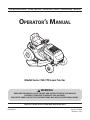 1
1
-
 2
2
-
 3
3
-
 4
4
-
 5
5
-
 6
6
-
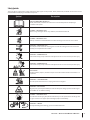 7
7
-
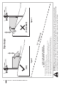 8
8
-
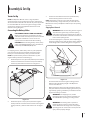 9
9
-
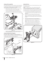 10
10
-
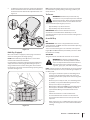 11
11
-
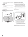 12
12
-
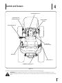 13
13
-
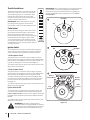 14
14
-
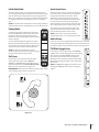 15
15
-
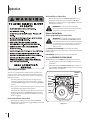 16
16
-
 17
17
-
 18
18
-
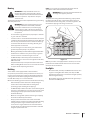 19
19
-
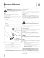 20
20
-
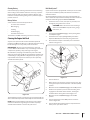 21
21
-
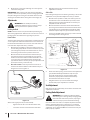 22
22
-
 23
23
-
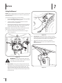 24
24
-
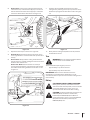 25
25
-
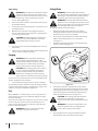 26
26
-
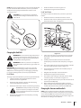 27
27
-
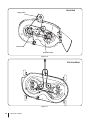 28
28
-
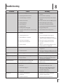 29
29
-
 30
30
-
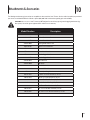 31
31
-
 32
32
-
 33
33
-
 34
34
-
 35
35
-
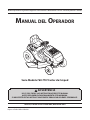 36
36
-
 37
37
-
 38
38
-
 39
39
-
 40
40
-
 41
41
-
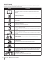 42
42
-
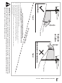 43
43
-
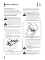 44
44
-
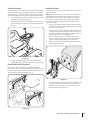 45
45
-
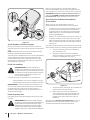 46
46
-
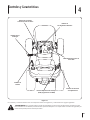 47
47
-
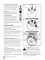 48
48
-
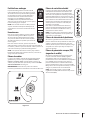 49
49
-
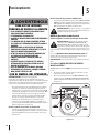 50
50
-
 51
51
-
 52
52
-
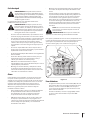 53
53
-
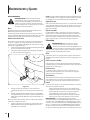 54
54
-
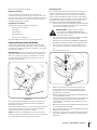 55
55
-
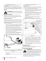 56
56
-
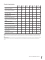 57
57
-
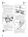 58
58
-
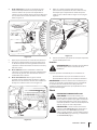 59
59
-
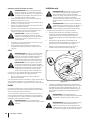 60
60
-
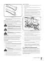 61
61
-
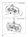 62
62
-
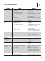 63
63
-
 64
64
-
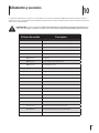 65
65
-
 66
66
-
 67
67
-
 68
68


Bolens 13W1762F065 El manual del propietario
- Categoría
- Cortadoras de césped
- Tipo
- El manual del propietario
- Este manual también es adecuado para
en otros idiomas
- English: Bolens 13W1762F065 Owner's manual